


12
HL-Series Tankless Heater
Installation
11/24/2015
Keltech •
215-1823 Rev. A; ECN 150023
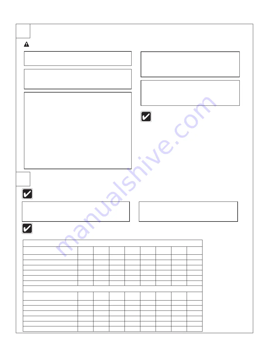
Perform Operational Test No. 1
Perform Operational Test No. 2
7
8
B
Start the water flow through the heater by
starting the process or fixture this heater is
connected to in order to activate heater .
A
Turn on hot water faucet/fixture/process . The
heater should activate immediately .
D
Press the up or down arrow keys to
adjust the set temperature . The controller
displays the temperature of water
measured at the outlet .
B
Turn off hot water faucet/fixture/process .
The flow switch will deactivate and shut
off power to the heater .
E
Test water temperature and stability at
outlet by viewing the display . Controller
displays (in red) the temperature of water
exiting the heater .
C
When flow rate reaches approximately
0 .5gpm, the flow switch recognizes this
condition and begins the heating process .
When the flow switch activates:
• The display changes from OFF to the output
temperature, verifying power supply connection
to the heating elements via the triac switches .
• Element load lights may be solid or flash
in unison as heating elements modulate
depending on the hot water demand .
• Digital temperature controller shows water
temperature . Additional programming is
not necessary .
Heater will not energize heating elements if the
inlet water temperature is equal to or greater than
the temperature set on the digital controller .
If the water flow exceeds maximum heating capacity of the heater, the temperature of water at the outlet
may be lower than the temperature selected on the controller. See table below to determine maximum
temperature rise capabilities.
Each model has precise specifications for temperature rise capabilities.
Temperature Rise (GPM & F°)
Models 208V, 240V, 277V, 480V
kW
1 gpm
Δ
T °F
1 .5 gpm
Δ
T °F
2 gpm
Δ
T °F
2 .5 gpm
Δ
T °F
3 gpm
Δ
T °F
3 .5 gpm
Δ
T °F
4 gpm
Δ
T °F
HL05
5
34
23
17
HL06
6
41
27
20
HL10
10
68
45
34
27
23
20
17
HL12
12
82
55
41
33
27
23
20
HL15
15
102
68
51
41
34
29
26
HL18
18
122
82
61
49
41
35
31
Temperature Rise (lpm & C°)
Models 208V, 240V, 277V, 480V
kW
3 .8 lpm
Δ
T °C
5 .7 lpm
Δ
T °C
7 .6 lpm
Δ
T °C
9 .5 lpm
Δ
T °C
11 .4 lpm
Δ
T °C
13 .3 lpm
Δ
T °C
15 .1 lpm
Δ
T °C
HL05
5
19
13
9
HL06
6
23
15
11
HL10
10
38
25
19
15
13
11
9
HL12
12
46
31
23
18
15
13
11
HL15
15
57
38
28
23
19
16
14
HL18
18
68
46
34
27
23
19
17
WARNING Ensure the cover is on or enclosure door is closed prior to performing this operational test.
A
Set the 2 or 3 pole switch or circuit breaker to
the ON position .


