


Kele KCO-NO2 User’s Manual
Last Rev: 6/15/2020
Kele • 3300 Brother Blvd. • Memphis, TN 38133
•
WWW.KELE.COM
Page 8 of 14
PRELIMINARY
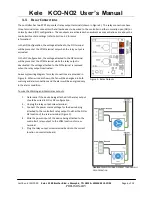
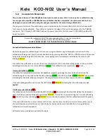
Figure 7
: Dip Switch Locations. CO specific
adjustments and connections are highlighted in
yellow while NO
2
specific adjustments and
connections are in green.
Dipswitch
Setting
Threshold Set Points
[ppm]
NO
2
CO
Warn
Alarm Warn
Alarm
0.7
2.0
15
30
1.0
3.0
25
40
2.0
4.0
30
45
2.5
4.5
35
45
Table 8: Alarm Threshold Setting
4.1
S
TARTUP
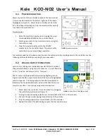
At startup, the controller has a 15 second warm-up period
before it begins normal behavior; during this time the
controller will:
Illuminate both the CO and NO
2
status LEDs
green
Output the minimum value of 4mA for both CO
and NO
2
. Analog outputs.
Deactivate both the
Alarm
and
Warning
relay
outputs.
4.2
S
ETTING
W
ARNING AND
A
LARM
T
HRESHOLDS
The controller has a warning and alarm threshold for each gas. These threshold values can be adjusted for each
sensor via dip switches on the controller’s main board (shown in Figure 7). Refer to details on setting the
thresholds for each sensor in Table 8.
NO
2
CO
Federal OSHA Personal Exposure Limit (PEL).
5 ppm
50 ppm
TABLE 7: Federal OHSA exposure limits
(29 CFR 1910.1051 TABLE Z-1)
4.3
W
ARNING AND
A
LARM
C
ONDITIONS
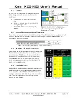
The controller has two LEDs on the front panel (one for each gas.
These LEDs change color to indicate the controller’s current
operational status. Table 5 shows the behavior of the front
panel LEDs during normal operation. Two dry-contact SPDT
relays are provided on the controller, these relays activate
during warning and alarm conditions: refer to
Section 3.3
for
location and wiring information.
4.4
S
ENSOR
R
EADINGS
Readings for the two sensors are independently reported on the
controller’s two 4 – 20mA analog current loop outputs during
normal operation. Refer to Table 3 and Table 4 for the output
scaling for each sensor. Table 6 lists the operational conditions
that force the analog outputs to their limits regardless of
ambient gas concentrations.


