


KCO-NO2 User’s Manual
90-0201-01
Kele • 3300 Brother Blvd. • Memphis, TN 38133
Page: 5
WWW.KELE.COM
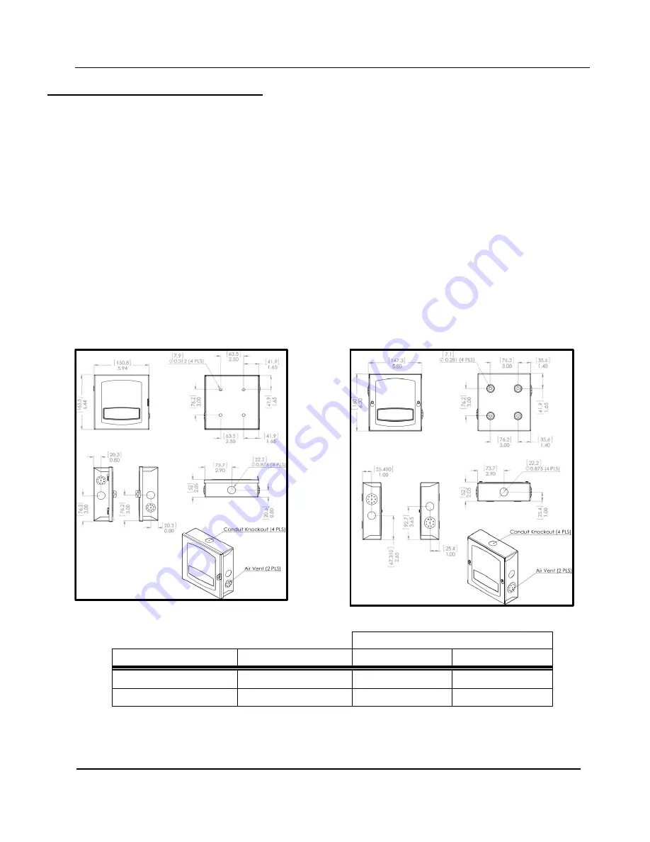
2 Mechanical Installation
The Model KCO-NO2 is available in two versions of a gray, powder-coated, 18 Gauge steel
enclosure. The removable, lockable, hinged-cover version is shown in
cover version is shown in
. All electronics are attached to the front cover. There are ½”
conduit knock-outs on all sides for electrical connections. In potentially damp locations the knock-
out on the bottom of the case should be used to minimize the possibility of water entry.
DO NOT USE THE VENT HOLES FOR WIRE ENTRY.
This unit is designed to mount to a rigid, vibration-free surface near the middle of the area to be
monitored about 5 feet above the floor.
It should be located where there is free airflow - avoid corners or recesses.
The air vents on the sides of the enclosure should not be closer than 1 foot from the nearest
perpendicular wall and must not be obstructed or painted-over.
May be mounted in any orientation but hinge on the left side is most common.
Mounting holes are made for direct wall screws for the surface encountered. (Mounting screws
not provided) or switch box spacing.
2.1 Enclosure Dimensions
Distance from center
Case Style
Mtg hole diameter
Horizontal
Vertical
Hinged
5/16” (7.94 mm)
1.25” (31.75 mm)
1.50” (38.10 mm)
Screw-down
9/32” (7.14 mm)
1.50” (38.10 mm)
1.50” (38.10 mm)
TABLE 1:
Mounting Hole Diameters & Locations
Figure 2:
KCO-NO2 Hinged Front Panel Enclosure
Figure 1: K
CONO2 Screw Front Panel Enclosure
Dimensions


