Model DMM7510 7½ Digit Graphical Sampling Multimeter Reference Manual
Section 4: Measure considerations
DMM7510-901-01 Rev. B / May 2015
4-3
The Model DMM7510 uses internal references to calculate an accurate and stable reading. When
the NPLC setting is changed, each reference is automatically updated to the new NPLC setting
before a reading is generated. Therefore, frequent NPLC setting changes can result in slower
measurement speed.
This setting also affects the normal mode rejection ratio (NMRR) and common mode rejection ratio
(CMRR). Normal mode noise is the noise signal between the HI and LO terminals; common-mode
noise is the noise signal between LO and chassis ground. See the Model DMM7510 specification for
NMRR and CMRR values at different PLC settings.
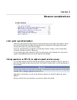
If you change the aperture or NPLCs, you may want to adjust the displayed digits to reflect the
change in usable digits. Refer to
Setting the number of displayed digits
(on page 2-55).
For functions that can accept either an aperture or an NPLC value, changing the value of one
changes the value for the other. For example, if you set an aperture of 0.035, then set an NPLC value
of 2, the aperture value is changed to 0.033333333.
To set NPLC using the front panel:
1. Press the
FUNCTION
key.
2. Select the measure function.
3. Press the
MENU
key.
4. Under Measure, select
Settings
.
5. Select
Integration Rate
. If the function allows both NPLC or aperture settings, the Integration
Rate dialog box is displayed. Otherwise, a number pad is displayed.
6. If the Integration Rate dialog box is displayed, set the Unit to be
NPLC
or
Aperture
.
7. For NPLC or Aperture, enter the value.
8. Select
OK
.
DMM resistance measurement methods
The method that the Model DMM7510 uses to measure resistance depends on the resistance range.
For resistance ranges from 1
Ω
to 1 M
Ω
,
the Model DMM7510 uses the constant-current method to
measure resistance. For resistance ranges from 10 M
Ω
to 100 G
Ω
, a ratiometric method is used.
When the constant-current method is used, the Model DMM7510 sources a constant current (I) to the
device under test and measures the voltage (V). Resistance (R) is then calculated and displayed
using the known current and measured voltage (R = V/I).
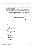
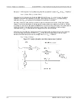
When the ratiometric method is used, test current is generated by a 6.9 V reference through a 10 M
Ω
reference resistance (R
REF
).

