Section 3: Functions and features
Model DMM7510 7½ Digit Graphical Sampling Multimeter Reference Manual
3-60
DMM7510-901-01 Rev. B / May 2015
The edge sets the type of edge that is detected as an input on the external in line. You can set the
external I/O to detect trigger inputs on the falling edge, rising edge, or either edge. When falling edge
is selected, the input is detected when the line state transitions from high to low. When rising edge is
selected, the input is detected when the line state transitions from low to high.
The logic type determines if the external I/O output asserts a TTL-high pulse or a TTL-low pulse for
the trigger.
You can use the external I/O with interactive triggering or with the trigger model. For more information
about the trigger modes and triggering, refer to
(on page 3-63).
External trigger I/O pinouts
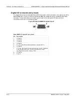
The EXT TRIG IN/OUT pinouts are shown in the following figure and table.
Figure 127: EXT TRIG I/O pinout diagram
Pin
Description
1
EXT TRIG OUT
2
EXT TRIG IN
3
Unused
4
Unused
5
Unused
6
Unused
7
Signal ground
8
Signal ground
The EXT TRIG IN can detect the falling edge, rising edge, or either edge pulse. The detected edge is
set through edge settings using remote commands. The default is falling edge. The following figure
shows the electrical and timing specifications for pulse detection of EXT TRIG IN.
Figure 128: External I/O pulse specifications


