


1-8
Getting Started
Model 6220/6221 User’s Manual
Return to
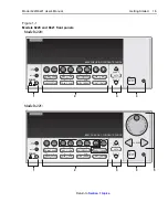
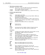
Rear panel summaries
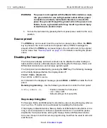
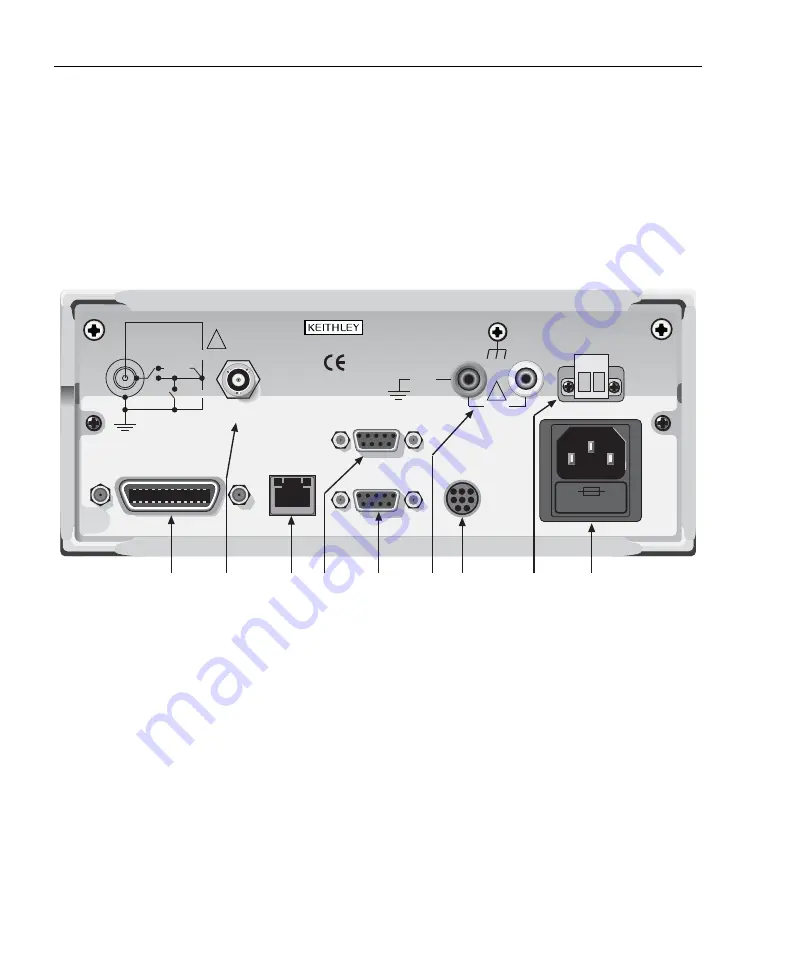
The rear panel of the Models 622x is shown in
. The Model 6221 rear
panel is shown, but the Model 6220 is identical except it does not have the Ether-
net connector. The descriptions of the rear panel components follow
.
Figure 1-2
Model 622x rear panel
1 IEEE-488
Connector for IEEE-488 (GPIB) operation. Use a shielded cable, such as the Model
7007-1 or 7007-2.
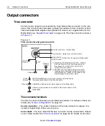
2 OUTPUT
3-lug female triax connector for current source output. Mates to the supplied triax cable
(237-ALG-2). Will also mate to any triax cable terminated with a 3-slot male triax connec-
tor.
3 ETHERNET
RJ45 female connector for Ethernet operation. Use an RJ45 male/male cable for connec-
tion. Two status LEDs are located at the top of the connector. These LEDs indicate status
of the Ethernet (see Section 10 of the Reference Manual for details).
The rear panels of the Model 6220 and 6221 are the same, except the
Model 6220 does not have an Ethernet connector (3).
MADE IN
U.S.A.
INTERNALLY
SWITCHED
1 AMP MAX.
HI
CABLE
GUARD
105Vpk
LO
105Vpk
250Vpk
OUTPUT
CAT I
IEEE-488
(CHANGE IEEE ADDRESS
WITH FRONT PANEL MENU)
ETHERNET
10/100 BaseT
Link/Act
100bT
DIGITAL I/O
RS-232
TRIGGER
LINK
LINE FUSE
SLOWBLOW
1.6A, 250V
LINE RATING
100-240VAC
50, 60Hz
120VA MAX.
250Vpk
105Vpk
LO
GUARD
INTERLOCK
!
!
1
2
3
4
5
6
7
8
9
6221 only
NOTE
Summary of Contents for 6220 DC
Page 2: ......
Page 4: ......
Page 6: ......
Page 16: ......
Page 36: ...1 20 Getting Started Model 6220 6221 User s Manual Return to Section 1 topics...
Page 131: ...6 10 Averaging Filter Math and Buffer Model 6220 6221 User s Manual Return to Section 6 topics...
Page 148: ...A Specifications...
Page 167: ......
Page 169: ......
Page 170: ......