Resistance calibration
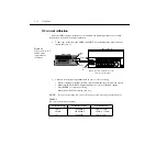
Follow these steps for resistance calibration:
1.
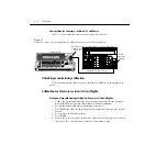
Set the calibrator to the resistance mode, and turn on external sensing.
NOTE
Use external sense (4-wire
Ω
) when calibrating all resistance ranges. Be sure that the
calibrator external sense mode is turned on,
2.
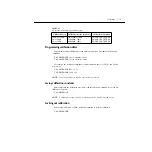
Perform the calibration steps summarized in
. For each step:
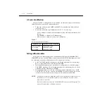
• Set the calibrator to the indicated resistance, and make sure the unit is in operate.
(Use the recommended resistance or the closest available value.)
• Send the indicated programming command. (Change the command parameter if you
are using a different calibration resistance than that shown.)
• Wait until the Model 2010 completes each step before continuing.
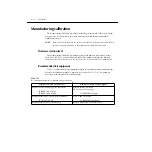
Table 2-9
Resistance calibration programming steps
Calibration
step
Calibrator
resistance
Calibration command*
Parameter range
10
Ω
1k
Ω
10k
Ω
100k
Ω
1M
Ω
10
Ω
1k
Ω
10k
Ω
100k
Ω
1M
Ω
:CAL:PROT:DC:STEP6 10
:CAL:PROT:DC:STEP7 1E3
:CAL:PROT:DC:STEP8 10E3
:CAL:PROT:DC:STEP9 100E3
:CAL:PROT:DC:STEP10 1E6
9 to 11
900 to 1.1E3
9E3 to 11E3
90E3 to 110E3
900E3 to 1.1E6
* Use exact calibrator resistance value for parameter.
2-16
Calibration
Summary of Contents for 2010
Page 14: ...1 Performance Verification 1 Performance Verification...
Page 28: ...2 Calibration 2 Calibration...
Page 53: ...3 Routine Maintenance 3 Routine Maintenance...
Page 56: ...4 Troubleshooting 4 Troubleshoot ing...
Page 74: ...5 Disassembly 5 Disassembly...
Page 83: ...CONFIDENTIAL PROPRIETARY...
Page 84: ......
Page 85: ......
Page 86: ......
Page 87: ...6 Replaceable Parts 6 Replaceable Parts...
Page 98: ...CONFIDENTIAL PROPRIETARY...
Page 99: ...CONFIDENTIAL PROPRIETARY...
Page 100: ......
Page 101: ...A Specifications A Specifications...
Page 107: ...B Calibration CommandReference B Calibration CommandRef erence...


