K90-KPCS-IM-2
18/04/22
- 5 -
VENTILATION REQUIREMENTS
INDOOR UNITS:
If the unit is to be located in the machine room,
adequate ventilation air must be provided to avoid an excessive
temperature rise in the machine room. To allow for peak summer
temperatures a maximum rise of 10°F is recommended.
In case of compressors with remote condensers, approx. 10% of
the total heat rejected is given off by compressor and associated
piping. The correct formula for calculating the ventilation require-
ment for indoor parallel compressor unit is:
CFM =
The air intake should be positioned so that air passes over the
units. All State, Local and National codes should be followed.
This ventilation is only for the parallel compressor system. Ad-
ditional ventilation must be taken in to account after considering
other heat loads of the building.
10% of THR (BTU/HR)
10 (°F)
ELECTRICAL INFORMATION
All wiring and connections to the unit must be made in accordance with national as well as local electrical codes and by-laws.
WARNING
Electrical wiring should be sized in accordance with the minimum
circuit ampacity (MCA) shown on the unit nameplate and appli-
cable electrical codes. The unit power connections are approved
for copper wire only.
Connect the field power supply through a properly sized branch
circuit protection disconnect switch. The entering service fuse
must not exceed the maximum overcurrent protection (MOP)
value on the unit data plate.
Field connected control circuit wires are terminated directly at the
control circuit terminal block in accordance with the appropriate
wiring diagram.
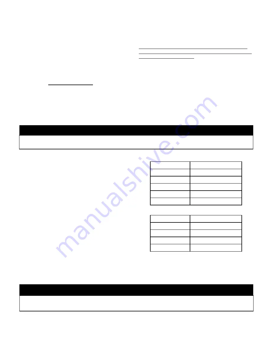
Voltage at the unit terminals must not vary more than the allow-
able variation during start-up and while under full load. If the volt-
age is normal at the supply with the compressor not running and
drops considerably when the switch is closed and the motor is
trying to start, there is a high resistance due to undersized wires
or faulty connections. Voltage drop between inoperative and full
load must not exceed 3% of line voltage. In addition, the phase
imbalance at the motor terminals should be within 2% on three
phase units.
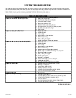
Refer to the wiring diagrams shipped with the unit for wiring ar-
rangements.
60 Hz Supply
Power
Allowable Variation
115-1-60
103-127 V
208/230-1-60
197-254 V
208/230-3-60
187-254 V
460-3-60
414-506 V
575-3-60
518-632 V
50 Hz Supply
Power
Allowable Variation
100-1-50
90-110 V
200/220-1-50
190-242 V
200/220-3-50
180-242 V
380/400-3-50
342-440 V
Any deviation or change to the electrical components or wiring as supplied on the original equipment, or noncompliance with the volt-
age and phase balance requirements without written authorization will void the warranty.
WARNING


