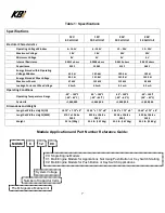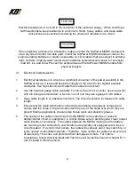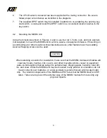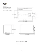
21
Installation Variation #2: Supplement for boats using a push button or rocker Switch for
engine Starting with multiple Engines.
For use with MKSMXXX02 Models
NOTE:
The PLC inside the MKSM needs power (approximately 2.5 amps) from a source, such
as a key switch, that provides power only when the boat is in operation. Consider this
additional 2.5 amps of power and how it may affect the reliability of the source. This
new circuit should be protected with a 5-amp fuse or circuit breaker per ABYC
standards, and it should in no way affect the integrity of the engine’s starting or running
operation.
1. Replace any existing engine starting push button or rocker switch with the KBI supplied
DPST.
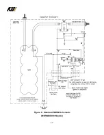
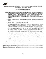
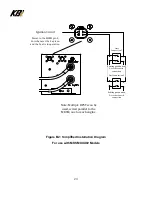
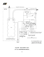
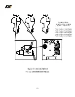
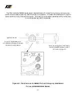
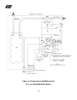
2. Wire the DPST as shown in figures B1, B2, and B3.
3. The Double Pole Single Throw (DPST) switch used in the starting circuit (each engine’s
starting circuit) fulfills the requirement to keep each engine starting independent and
isolated to just that one engine. One side (circuit) of that DPST switch simply provides
the same function as the existing push button or rocker start switch on the vessel.
There is no change to functionality. The other side (circuit) of the DPST switch turns on
the capacitor providing power to the engine’s (vessel’s) electrical circuit regardless of
lead-acid battery condition. The capacitor, the MKSM circuit, does not actually engage
the starter motor. The original OEM circuit does that, just as it normally would. All the
MKSM is doing is making sure there is power available. After the engines start, the KBI
MKSM PLC senses the engine has started (via voltage from Pin 4) and takes over
control of the MKSM circuit and recharges the unit. In order to ensure the PLC does not
receive a false positive error when the next engine is started, a cube relay inside the
MKSM interrupts PLC power supply, causing the PLC to reset. See theory of operation
on pages 13 and 14.
The PLC inside the MKSM needs power from a source that provides power only when the
engine is running. See Figures B1, B2, and B3.

