Page 5 of 8
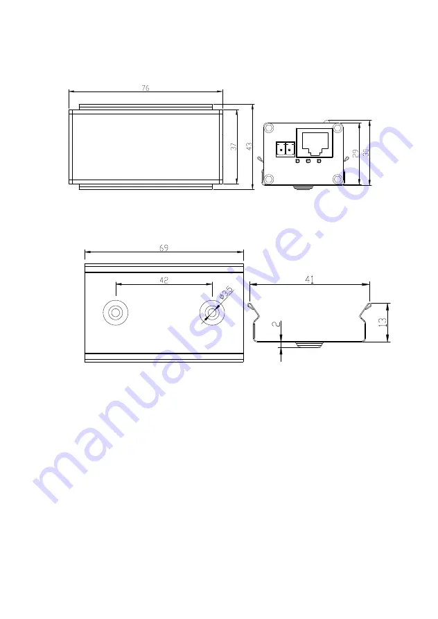
Dimensions (Unit = mm)
Equipment:
Installation Accessories:
Page 1: ...ay design ensures ease of installation with no electrical adjustment needed LED indicators are provided to show the operational status of the unit This unit is available in compact wall mount via metal clip Features 1 UTP port with PoW 1 10 100M Ethernet port Connect one transmitter or EERF1 LS1 T MN B UTP data rate 40Mbps 300m Based on cable quality cable pairs used 1 2 or 4 pairs and voltage app...
Page 2: ...visible damage which may have been caused during shipping Physical Deployment This equipment must be installed and operated in accordance with instructions found in this document Failure to comply with these instructions will invalidate the warranty Application ...
Page 3: ...ED indicator 3 Network cable connector 4 Ethernet RJ45 port 5 Grounding terminal LED Color Status Description PWR Green On Power supply is normal POW Green On PoW power supply is normal U LINK Green On EoU connection is normal Ethernet Link Act Green On Blink On Ethernet link is normal Blink Data is active ...
Page 4: ... 3 PoW 4 PoW 5 PoW 6 PoW 7 PoW 8 PoW Notes Please use straight through cable rather than cross over cable 8 wires transmission all 8 wires need to be connected 4 wires transmission any 2 wires of PIN 1 2 4 and 5 as any 2 wires of PIN 3 6 7 and 8 as 2 wires transmission any 1 wire of PIN 1 2 4 and 5 as any 1 wire of PIN 3 6 7 and 8 as ...
Page 5: ...Page 5 of 8 Dimensions Unit mm Equipment Installation Accessories ...
Page 6: ... protection time 2mS Transmission distance 400m Ethernet Port Transmission medium Cat5e 6 Standard IEEE802 3 IEEE802 3U Ethernet delay 1mS Protection ESD IEC61000 4 2 Anti thunder protection IEC61000 4 5 level 3 Operation Environment Operating temperature 20 70 Storage temperature 40 85 Humidity Non Condensing 0 90 Mechanical Dimension L W H 76mm 37mm 29mm Material Aluminum Color Black Weight 0 2K...
Page 7: ...ms before installation If any are missing please contact the dealer EoU receiver x1 Wall mounting clamp x1 QSG User manual x1 Screws x2 Please follow the installation steps below 1 Attach the clamp to the wall using the 3X10mm screws 2 Press the receiver into the clamp ...
Page 8: ...work Confirm the installation is done according to factory installation requirements Confirm if the RJ45 cable order is following the EIA TIA568A or 568B industry standards The maximum transmission distance depends on the signal source and cable quality Please do not exceed the maximum transmission distance Please replace the failed device with a known working unit to determine if you have a damag...