


KBAC SERIES INSTALLATION AND OPERATION MANUAL
21
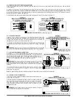
11.2 – RESTARTING THE DRIVE AFTER A FAULT HAS CLEARED
1,2
The drive monitors five faults: Undervoltage, Overvoltage, Short Circuit at the motor (phase-to-phase), Overload and Phase Loss Detection.
See Section 13.2 on page 23 for the Status (ST) LED indication. Also see Section 10.3 on page 19 for Automatic Ride-Through or Manual
Restart selection with Jumper J3.
To restart the drive after a fault has been cleared, use the Start/Stop Switch.
2,3
If the Start/Stop Switch has been eliminated (bypassed), see
Section 7.6 on page 17.
4
The drive can be restarted (after the fault has been cleared) by disconnecting the AC power, and all LEDs are no
longer illuminated, and then reconnecting the AC power.
Notes: 1.
For an Overload Fault, be sure the fault has been cleared before restarting the drive. Check the motor current with an AC RMS
responding ammeter. Also, the CL setting may be set too low. See Section 13.7 on page 30.
2.
For an Overvoltage Fault, if the drive is set for
Automatic Ride-Through, the drive will automatically restart when the AC Line voltage returns to below the specified Overvoltage Trip Point.
3.
If the Forward-Stop-Reverse Switch has been installed, it can be used to restart the drive.
4.
If the Start/Stop Switch has been eliminated
(bypassed), the AC Line must be used to restart the drive after an Overload Fault has been cleared.
12 – TRIMPOT ADJUSTMENTS
The drive contains trimpots which are factory set for most applications. See Figures 4 – 7 on pages 8 – 11 for the location of the trimpots and
their approximate factory calibrated positions. Some applications may require readjustment of the trimpots in order to tailor the drive for a
specific requirement. The trimpots may be readjusted as described in this section.
WARNING!
If possible, do not adjust trimpots with the main power applied. If adjustments are made with the main power applied, an
insulated adjustment tool must be used and safety glasses must be worn. High voltage exists in this drive. Fire and/or electrocution can result
if caution is not exercised. The Safety Warnings on page 5 must be read and understood before proceeding.
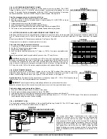
12.1 – MINIMUM SPEED TRIMPOT (MIN)
Sets the minimum speed of the motor. The MIN Trimpot is factory set to 0% of frequency setting.
For a higher minimum speed setting, rotate the MIN Trimpot clockwise. See Figure 33.
12.2 – MAXIMUM SPEED TRIMPOT (MAX)
Sets the maximum speed of the motor. The MAX Trimpot is factory set to 100% of frequency
setting. For a lower maximum speed setting, rotate the MAX Trimpot counterclockwise. For a
higher maximum speed setting, rotate the MAX Trimpot clockwise. See Figure 34.
12.3 – ACCELERATION TRIMPOT (ACCEL)
Sets the amount of time for the motor to accelerate from zero speed to full speed. The ACCEL
Trimpot is factory set to 1.5 seconds. For a longer acceleration time, rotate the ACCEL Trimpot
clockwise. For more rapid acceleration, rotate the ACCEL Trimpot counterclockwise. See Figure
35.
Note:
Rapid acceleration settings may cause the current limit circuit to activate, which will extend
the acceleration time.
12.4 – DECELERATION TRIMPOT (DECEL)
Sets the amount of time for the motor to decelerate from full speed to zero speed. The DEC/I
Trimpot is factory set to 1.5 seconds. For longer deceleration time, rotate the DEC/I Trimpot
clockwise. For more rapid deceleration, rotate the DEC/I Trimpot counterclockwise. See Figure 36.
Application Note:
On applications with high inertial loads, the deceleration time may automatically
increase. This will slow down the decrease speed to prevent the bus voltage from rising
to the
Overvoltage Trip point. This function is called Regeneration Protection. It is recommended that for
very high inertial loads that both the ACCEL and DEC/I Trimpots be set to greater than 10 seconds.
12.5 – DC INJECTION BRAKE TRIMPOT (DECEL)
The drive is factory set for Regenerative Braking (Jumper J7 set to the "RG" position). When the
drive is set for DC Injection Brake (Jumper J7 set to the "INJ" position), the DECEL Trimpot is used to set the amount of time the DC current is
applied to the motor. See Figure 37. Also see Section 10.6 on page 20.
FIGURE 37
DC INJECTION BRAKE TRIMPOT RANGE
FIGURE 33
MINIMIM SPEED TRIMPOT RANGE
FIGURE 34
MAXIMUM SPEED TRIMPOT RANGE
FIGURE 35
ACCELERATION TRIMPOT RANGE
FIGURE 36
DECELERATION TRIMPOT RANGE


