KB Electronics KBAC-217 Installation And Operation Manual Download Page 4

KBAC SERIES INSTALLATION AND OPERATION MANUAL 

1 – QUICK-START INSTRUCTIONS 

Also see Section 4 – Important Application Information on page 5. 


Important:

 You must read these simplified instructions before proceeding. These instructions are to be used as a reference only and are not 

intended to replace the details provided herein. You must read the Safety Warnings on page 5 before proceeding. 


Reconditioning the Bus Capacitors: 

If this drive has been in storage for over one year, it is necessary to recondition the power supply bus 

capacitors. To recondition the bus capacitors, apply the AC Line, with the drive in the Stop Mode, for a minimum of one hour. Not following 
this procedure will cause the bus capacitors to fail. 


WARNING! High Voltage! 

Disconnect the main power before making connections to the control. Do not depend on the POWER or 

STATUS LEDs, located on the front cover, to no longer be illuminated as a guaranteed power off condition. 


1.1 – MOUNTING INSTRUCTIONS 

See Section 5 on page 12. 
 

1.2 – AC LINE INPUT FUSING 

It is recommended that a fuse(s) or circuit breaker be 
installed in the AC Line. Fuse each conductor that is not at 
ground potential. For the recommended fuse size, see 
Table 2 on page 7. Also see Section 6 on page 15. 
 

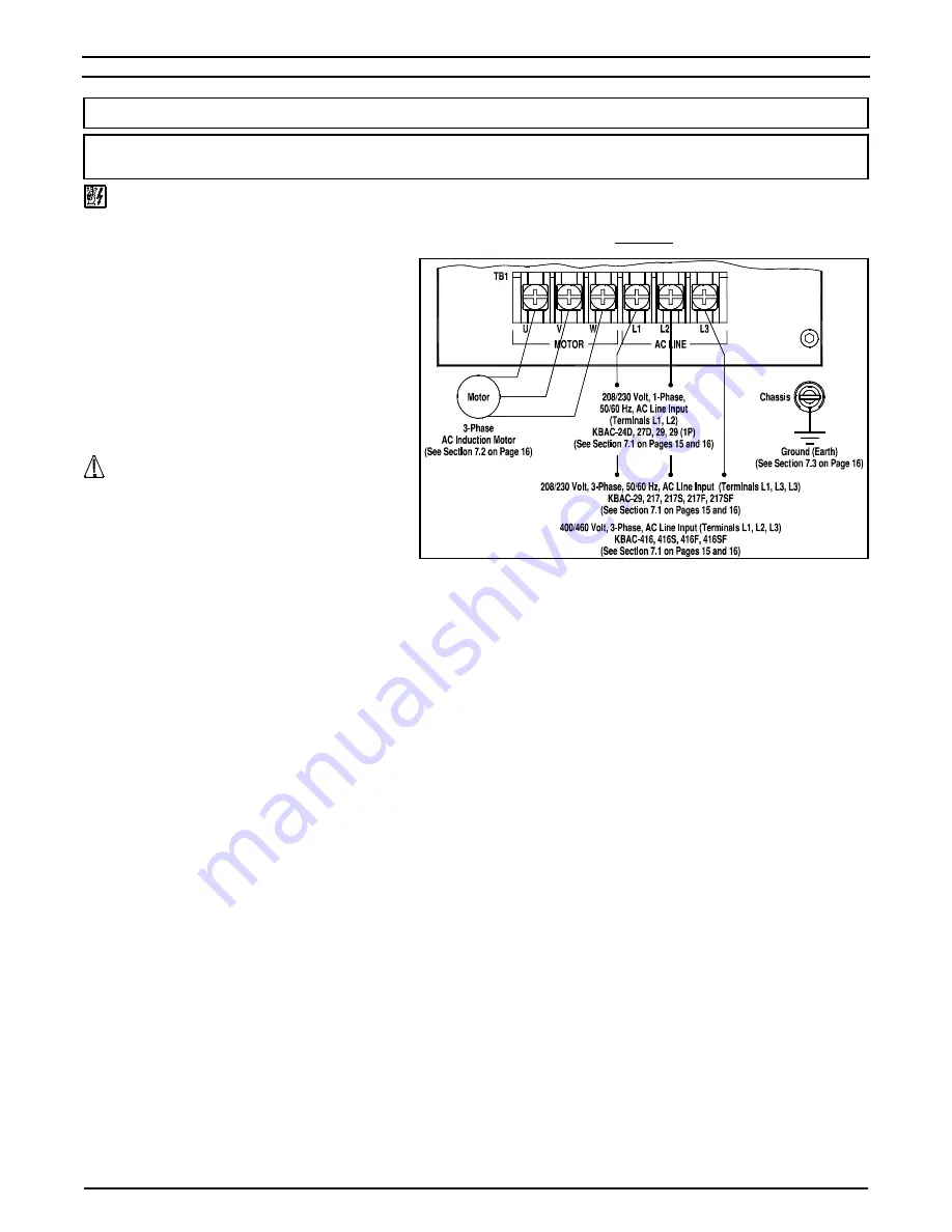
1.3 – AC LINE INPUT CONNECTION 

Connect the AC Line input to Terminal Block TB1, as 
shown in Figure 1. Also see Section 7.1 on pages 15 and 
16. 


GFCI Operation: 

Third Generation (3G) drives are jumper 

selectable (J12) for standard and sensitive GFCIs. 


CAUTION!

 The rated AC Line voltage of the drive 

must  match  the  actual  AC  Line  input  voltage.                  
On KBAC-24D, 27D the setting of Jumper J1 must match 
the actual AC Line input voltage. 


KBAC-24D, 27D, 29 (1P):

 Designed to accept 1-phase 

(Terminals L1, L2) AC Line input only. Rated for 208/230 
Volt AC Line input with Jumper J1 set to the "230V" position (factory setting). Rated for 115 Volt AC Line input with Jumper J1 set to the 
"115V" position. KBAC-27D is rated for 1½ HP maximum with 115 Volt AC Line input and 2 HP maximum with 208/230 Volt AC Line input. 


KBAC-29:

 Designed to accept 1-phase (Terminals L1, L2) or 3-phase (Terminals L1, L2, L3) AC Line input. Rated for 208/230 Volt AC Line 

input only. Rated for 2 HP maximum with 1-phase AC Line input and 3 HP maximum with 3-phase AC Line input. 


KBAC-217, 217S, 217F, 217SF:

 Designed to accept 3-phase (Terminals L1, L2, L3) AC Line input only. Rated for 208/230 Volt AC Line input 

only. 


KBAC-45, 48, 416, 416S, 416F, 416SF:

 Designed to accept 3-phase (Terminals L1, L2, L3) AC Line input only. Rated for 400/460 Volt AC 

Line input only. 
 

1.4 – MOTOR CONNECTION 

Connect the motor to Terminal Block TB1 Terminals U, V, W, as shown in Figure 1 above. See Section 7.2 on page 16. Motor cable length 
should not exceed 100 ft. (30 m) – special reactors may be required – contact Technical Support. 
 

1.5 – GROUND CONNECTION 

Connect the ground wire (earth) to the ground screw, as shown in Figure 1 above. See Section 7.3 on page 16. Be sure the motor is also 
properly grounded. 
 

1.6 – 60 Hz AND 50 Hz MOTOR OPERATION 

The drive is factory set for 60 Hz motor operation (Jumper J4 set to the "1X" position and Jumper J5 set to the "60Hz" position). For 50 Hz 
motor operation, be sure Jumper J4 is set to the "1X" position and set Jumper J5 to the "50Hz" position. See Section 10.4 on page 19. 
 

1.7 – START/STOP SWITCH 

A prewired Start/Stop Switch is supplied to electronically "start" and "stop" the drive, as described in Section 7.5 on page 17. This switch must 
be used to "start" the drive each time the AC Line is applied to the drive or to "restart" the drive. Also see Section 10.8 on page 20. 
 

1.8 – JUMPER SETTINGS 

All jumpers have been factory set for most applications. However, some jumpers may need to be set in order to tailor the drive for a specific 
application. See Section 10 on pages 19 and 20. 


IMPORTANT:

 To ensure that the motor is properly protected with the I

2

t Overload Protection feature, it is required that Jumper J2 is set to the 

corresponding position for the motor horsepower being used, as shown in Figure 23 on page 19. 
 

1.9 – TRIMPOT ADJUSTMENTS 

All trimpots have been factory set for most applications. Some applications require adjustment of the trimpots to tailor the drive for a specific 
requirement. See Section 12 on page 21 and 22. 
 

1.10 – DIAGNOSTIC LEDs 

After power has been applied, observe the LEDs to verify proper drive operation, as described in Section 13 on page 23. 


FIGURE 1 

GENERAL CONNECTION DIAGRAM 

Summary of Contents for KBAC-217

Page 1: ...2G and 3G Models3 5 KBAC 24D 27D 29 29 1P 45 48 217 217S 217F 217SF 416 416S 416F 416SF The information contained in this manual is intended to be accurate However the manufacturer retains the right to make changes in design which may not be included herein Notes 1 UL approved as an electronic overload protector for motors 2 Special software is available for PSC motors contact Technical Support 3 ...

Page 2: ...Manual Start Selection J3 19 10 4 Motor Frequency Selection J4 and J5 19 10 4 1 Setting the Drive for 50 Hz or 60 Hz Motor Operation J4 and J5 19 10 4 2 Setting the Drive for Two Times the Rated Motor RPM J4 and J5 19 10 5 Boost Mode Selection J6 20 10 6 Braking Mode Selection J7 20 10 7 Run Fault Output Relay Operation Selection J8 20 10 8 Stop Contact Type Selection J9 20 10 9 Torque Mode Select...

Page 3: ...lection J10 20 32 Switching Frequency and GFCI Selection Third Generation 3G Drives Only J12 20 33 Minimum Speed Trimpot MIN Range 21 34 Maximum Speed Trimpot MAX Range 21 35 Acceleration Trimpot ACCEL Range 21 36 Deceleration Trimpot DECEL Range 21 37 DC Injection Brake Trimpot DECEL Range 21 38 Slip Compensation Trimpot COMP Range 22 39 Current Limit Trimpot CL Range 22 40 I2 t Trip Time vs Moto...

Page 4: ...rminals L1 L2 L3 AC Line input Rated for 208 230 Volt AC Line input only Rated for 2 HP maximum with 1 phase AC Line input and 3 HP maximum with 3 phase AC Line input KBAC 217 217S 217F 217SF Designed to accept 3 phase Terminals L1 L2 L3 AC Line input only Rated for 208 230 Volt AC Line input only KBAC 45 48 416 416S 416F 416SF Designed to accept 3 phase Terminals L1 L2 L3 AC Line input only Rated...

Page 5: ...ntilated 3 phase AC induction motors will overheat if used beyond a limited speed range at full torque Therefore it is necessary to reduce motor load as speed is decreased Note Some fan cooled motors can be used over a wider speed range Consult the motor manufacturer for details CAUTION 1 Some motors have low speed characteristics which cause overheating and winding failure under light load or no ...

Page 6: ...vided for easy installation of accessories Custom software all models can be factory programmed for applications which require special timing PLC functions and GFCI operation 4 1 STANDARD FEATURES Industrial Duty Die Cast Aluminum Case with Hinged Cover Available in dark gray finish or FDA approved white finish Simple to Operate Does not require programming Uses trimpots and jumpers which are fact...

Page 7: ...n Specification Factory Setting 115 Volt AC Line Input Voltage Operating Range Volts AC 115 15 208 230 Volt AC Line Input Voltage Operating Range Volts AC 208 15 230 15 400 460 Volt AC Line Input Voltage Operating Range Volts AC 380 15 460 15 Maximum Load Current Overload for 2 Minutes 150 Switching Frequency kHz Jumper J12 3G Drives Only 1 8 12 8 Signal Following Input Voltage Range2 Volts DC 0 5...

Page 8: ... selection See Section 10 4 on page 19 7 Jumper J12 Switching Frequency and GFCI selection Third Generation 3G drives only See Section 10 11 on page 20 8 Jumper J6 Adjustable Boost selection See Section 10 5 on page 20 9 Jumper J7 Regeneration or DC Injection Braking See Section 10 6 on page 20 10 Jumper J8 Run or Fault Output Relay Operation selection See Section 10 7 on page 20 11 Jumper J9 Norm...

Page 9: ...per J4 Frequency Multiplier selection See Section 10 4 on page 19 8 Jumper J7 Regeneration or DC Injection Braking See Section 10 6 on page 20 9 Jumper J5 Motor Frequency selection See Section 10 4 on page 19 10 Jumper J8 Run or Fault Output Relay Operation selection See Section 10 7 on page 20 11 Jumper J9 Normally Open or Closed Stop Contact selection See Section 10 8 on page 20 12 Jumper J10 Co...

Page 10: ...n 10 5 on page 20 7 Jumper J4 Frequency Multiplier selection See Section 10 4 on page 19 8 Jumper J7 Regeneration or DC Injection Braking See Section 10 6 on page 20 9 Jumper J5 Motor Frequency selection See Section 10 4 on page 19 10 Jumper J8 Run or Fault Output Relay Operation selection See Section 10 7 on page 20 11 Jumper J9 Normally Open or Closed Stop Contact selection See Section 10 8 on p...

Page 11: ...MIN Acceleration ACCEL Deceleration DECEL DC Injection Brake DECEL Boost BOOST Current Limit CL Jog JOG Slip Compensation COMP See Section 12 on pages 21 and 22 8 Selectable Jumpers Motor Horsepower J2 Automatic Ride Through or Manual Start J3 Frequency Multiplier J4 Motor Frequency J5 Fixed or Adjustable Boost J6 Regeneration or DC Injection Braking J7 Run or Fault Output Relay Operation J8 Norma...

Page 12: ...care should be taken to avoid extreme hazardous locations where physical damage can occur When mounting the drive in an enclosure the enclosure should be large enough to allow for proper heat dissipation so that the ambient temperature does not exceed 40 C 104 F at full rating See Figures 8 10 on pages 12 14 WARNING Do not use this drive in an explosion proof application Be sure the control is sec...

Page 13: ...KBAC SERIES INSTALLATION AND OPERATION MANUAL 13 FIGURE 9 KBAC 27D 29 29 1P 45 48 MECHANICAL SPECIFICATIONS Inches mm Tighten these screws in the sequence shown to 12 in lbs 14 kg cm ...

Page 14: ...KBAC SERIES INSTALLATION AND OPERATION MANUAL 14 FIGURE 10 KBAC 217 217S 217F 217SF 416 416S 416F 416SF MECHANICAL SPECIFICATIONS Inches mm ...

Page 15: ...he cover making sure that the wires do not get caught or crimped as the cover is closed Tighten the four screws so that the gasket is slightly compressed The recommended tightening torque is 12 in lbs 14 kg cm do not overtighten See Figures 8 10 on pages 12 14 for the tightening sequence Application Note To avoid erratic operation do not bundle the AC Line and motor wires with each other or with w...

Page 16: ...Ground Wire Earth to the Green Ground Screw The Ground Screws are located next to Terminal Block TB1 See Figures 11 13 on pages 15 and 16 7 4 REMOTE MAIN SPEED POTENTIOMETER CONNECTION The drive is supplied with a prewired Main Speed Potentiometer mounted on the front cover To operate the drive from a remote potentiometer 5 kΩ remove the white orange and violet potentiometer leads from Terminals P...

Page 17: ...tiometer setting when the AC Line is applied 7 7 VOLTAGE FOLLOWING CONNECTIONS An isolated 0 5 Volt DC analog signal input can also be used to control motor speed in lieu of the Main Speed Potentiometer The drive output will linearly follow the analog signal input Wire the signal input positive lead to Terminal P2 and the negative lead to Terminal P1 With external circuitry a 0 10 Volt DC analog s...

Page 18: ...atic ramping then the hi pot output must be manually increased to the test voltage and then manually reduced to zero This procedure must be followed for each machine to be tested A suggested hi pot tester is Slaughter Model 2550 CAUTION Instantly applying the hi pot voltage will cause irreversible damage to the drive which will void the warranty FIGURE 21 TYPICAL HI POT TEST SETUP AC Line Input 9 ...

Page 19: ...seconds the drive will shut down and then ride through and automatically return to the set frequency See Figure 24 If Jumper J3 is set to the M position the drive will have to be manually restarted for a momentary power loss using the Start Stop Switch Also see Section 13 2 on page 23 for the Status ST LED indication On KBAC 24D 217 217S 217F 217SF 416 416S 416 416F 416SF Jumper J3 is labeled AUTO...

Page 20: ...LY Jumper J12 is factory set to the 8K position for a switching frequency at the motor of 8 kHz For 12 kHz switching frequency set Jumper J12 to the 12K position This jumper also allows the drive to be used on standard G1 position or sensitive G2 position GFCIs See Figure 32 Note GFCI operation may increase audible motor noise FIGURE 32 SWITCHING FREQUENCY AND GFCI SELECTION KBAC 24D 27D 29 29 1P ...

Page 21: ...not exercised The Safety Warnings on page 5 must be read and understood before proceeding 12 1 MINIMUM SPEED TRIMPOT MIN Sets the minimum speed of the motor The MIN Trimpot is factory set to 0 of frequency setting For a higher minimum speed setting rotate the MIN Trimpot clockwise See Figure 33 12 2 MAXIMUM SPEED TRIMPOT MAX Sets the maximum speed of the motor The MAX Trimpot is factory set to 100...

Page 22: ...tor is properly protected with the I2 t feature it is required that the CL Trimpot be set for 160 of the motor nameplate rated current as described below 12 8 BOOST TRIMPOT BOOST The drive is factory set for Fixed Boost Jumper J6 set to the FIX position When the drive is set for Adjustable Boost Jumper J6 set to the ADJ position the BOOST Trimpot can be used to adjust the amount of boost voltage t...

Page 23: ...ource and the drive Mounts on the drive s PC board with four snap ins 2G 9600C 9600C 9600C 9600C 9600C 9600C 3G1 8890 8890 8890 8890 8890 8890 8890 Auto Manual Switch Kit When used with the Signal Isolator it selects remote process signal or the Main Speed Potentiometer Mounts on the enclosure cover and is supplied with a switch seal to maintain liquidtight integrity 9481 9481 9481 9481 9481 9481 ...

Page 24: ...ion and removal inconvenience or consequential damage including injury to any person caused by items of our manufacture or sale Some states do not allow certain exclusions or limitations found in this warranty and therefore they may not apply to you In any event the total liability of KB Electronics Inc under any circumstance shall not exceed the full purchase price of this product Rev 2 2000 COPY...

Reviews: