Kaysun KCCT-64 IPS Installation And Operation Instructions Manual Download Page 5

1. Installation 

• Connecting to one Outdoor Unit 

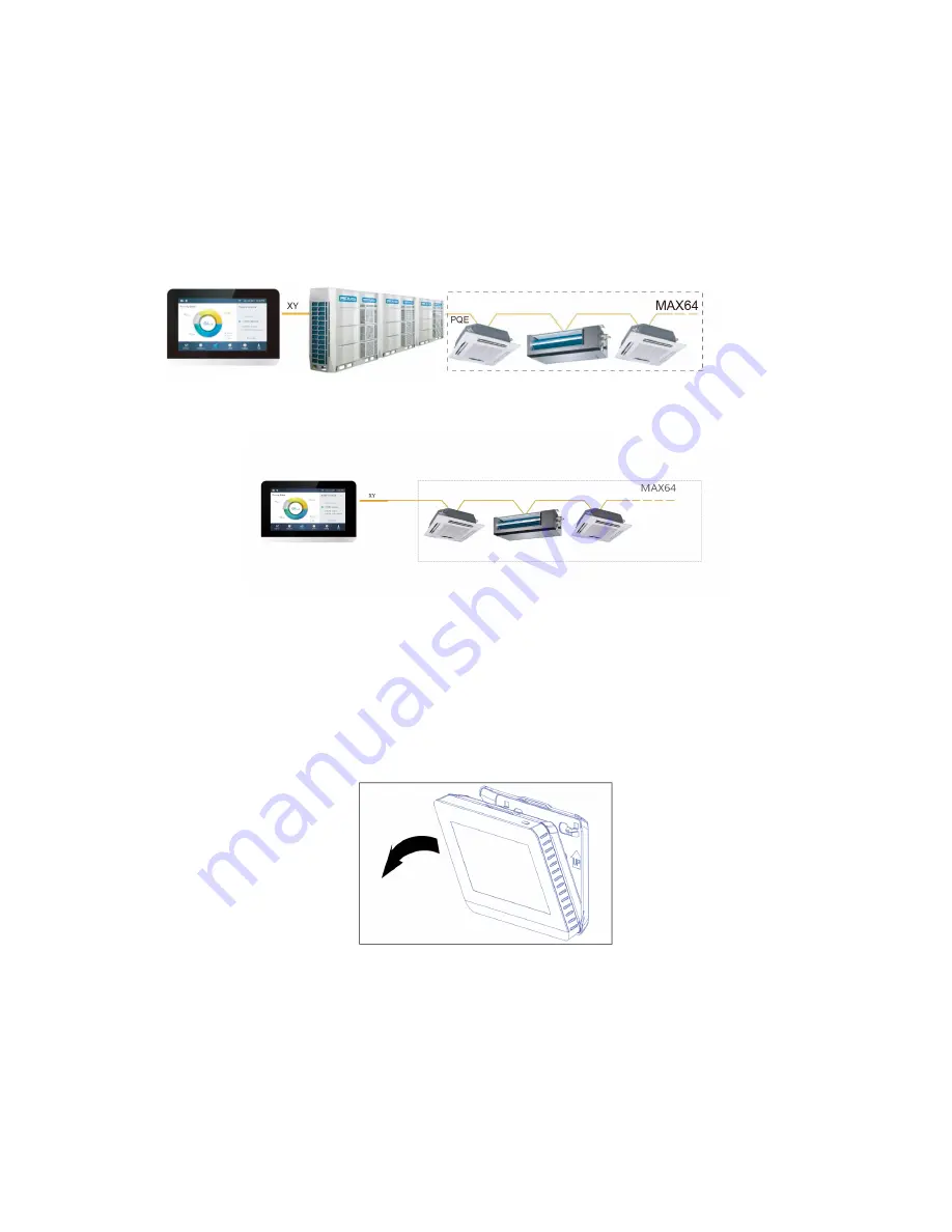
Connect the controller to the main control board of the outdoor unit using 

2-conductor shielded cable XY, Fig-1(a). Alternatively, user can connect the 

controller to the indoor units directly throught XY cable in V4+ and V5 models, 

Fig-1(b). 

See Fig-1. 

Fig-1(a)

Controller to Single Outdoor Unit Wiring Diagram 

Fig-1(b) 

Controller directly to Indoor Units Wiring Diagram 

• 

Mounting the Controller 

Remove the back cover from the controller using a phillips-head screwdriver as 

shown. 

See fig-2. 

Fig-2 

Remove Back Cover from Controller

Summary of Contents for KCCT-64 IPS

Page 1: ...TALLATION AND OPERATION INSTRUCTIONS Centralised Control KCCT 64 IPS Thank you very much for purchasing our product Before using your unit please read this manual carefully and keep it for future reference ...

Page 2: ......

Page 3: ... cover and the mounting surface Ground the shielded control wiring Do not use a megger to test insulation Do not install controller in areas where harmful gases containing sulfur or other damaging may exist ot the controller may be damaged Clean controller using a clean damp cloth Do not spray cleanser on or around controller Read all of the information in this manual before using this controller ...

Page 4: ...INSTALLATION ...

Page 5: ... connect the controller to the indoor units directly throught XY cable in V4 and V5 models Fig 1 b See Fig 1 Fig 1 a Controller to Single Outdoor Unit Wiring Diagram Fig 1 b Controller directly to Indoor Units Wiring Diagram Mounting the Controller Remove the back cover from the controller using a phillips head screwdriver as shown See fig 2 Fig 2 Remove Back Cover from Controller ...

Page 6: ...he back cover to the wall using screws See fig 3 Fig 3 Attach Back Cover to Wall Insert the controller into the bottom snap joints of the back cover at an angle See fig 4 Fig 4 Insert Controller into Back Cover ...

Page 7: ...he controller back toward the wall until it snaps into place See fig 5 Fig 5 Snap Controller Into Place Specification Table 1 Input Voltage 12VDC Ambient Temperature 23 110 F 5 43 C Ambient Humidity RH40 RH90 ...

Page 8: ...OPERATION ...

Page 9: ...1 Home Page Button and Display Description This section includes the descriptions for login page and home page and provides the instructions related to these two pages ...

Page 10: ...the IDUs 13 Schedule Enter the Schedule page to setup the daily schedules 14 Reports Enter the report page to view the error history of ODUs and IDUs and total running hours 15 Configuration Enter the Install page to search rename and group the IDUs 16 Setting Enter the setting page to setup the parameters for centralized controller IDUs ODUs and user accounts 17 Help Enter the help page to view t...

Page 11: ... the Screen OFF After login touch the ON OFF button to turn the screen backlight off or set the backlight automatically turns off in a period of time More details can be found in the general setting section ...

Page 12: ...on Choose Group List Tap on the drop down icon to select one of the groups The group editing information can be found in Configuration section Sort IDUs in order Tap on the Sort By icon the IDUs can be sorted in order of Name Mode and Model Set Display manner for IDUs Tap on Table icon the IDUs can be viewed either in graphic or table manner but only graphic icons are selectable and controllable ...

Page 13: ...HITE ERROR SCHEDULED LOCK ON SWING ON Description The color at the top of the icon box shows the current operation mode see Table 4 and the status of the device is indicated as an icon The device to be controlled is indicated as an icon The device shown may not represent the appearance of the actual unit Display the room temperature Display the operation mode of the device Display the setting temp...

Page 14: ...UE AUTO LIGHT BLUE COOL RED HEAT YELLOW DRY GREEN FAN GREY ERROR OFFLINE Table 5 Device Icon and the Corresponding Type Table 5 Icon Device Type IDU ODU L DUCT IDU M DUCT IDU H DUCT FAPU IDU WALL IDU FS IDU 4 WAY IDU COMPACT IDU C F IDU HP HR ODU SHP ODU ...

Page 15: ...s See details in Table 6 Setting Mode Tap Mode icons to choose one of the five modes More Setting Options Tap Setting icon on the bottom right corner to edit the fan speed swing and lock options Table 6 Temperature Setting Range in different operation modes Table 6 Operation mode Set temperature range COOL DRY 62ºF 86ºF 17ºC 30ºC HEAT 62ºF 86ºF 17ºC 30ºC AUTO Reserved Function COOL 62ºF 86ºF 17ºC ...

Page 16: ...e the fan speed is permanently set to AUTO Setting the Fan Speed Tap the corresponding fan speed icon to set the fan speed from 1 to 7 Enabling Disabling Louver Vertical Swing The air flow can also swing up and down by tapping the ON OFF button Lock Control Panel Tap the Advanced button and open the lock control settings ...

Page 17: ...k Fan Speed lock Unlock button Disable the lock High Mid Low Lock the fan speed in one of three speed modes Cooling set temp lock Unlock button Disable the lock Temperatures button Set the upper limit temperature range 17 C 30 C 62 F 86 F Heating set temp lock Unlock button Disable the lock Temperatures button Set the upper limit temperature range 12 C 30 C 54 F 86 F Remote controller lock Unlock ...

Page 18: ...ting dates for holiday 4 Add Schedule Register new schedules 5 Schedule List Display registered schedules by time and provide shortcut to turn ON OFF 6 Schedule Contents Display the schedule contents 7 Delete Delete schedule 8 Delay Override Delay the starting time for the selected schedule 9 Edit Edit the selected schedule Create a New Schedules 1 Tap on Add Schedule Button 2 Create an Event Name...

Page 19: ...sired IDUs or group of IDUs The selected unit will have a tick in the box 5 Touch the Edit button in Action bar to setup the running mode temperature and other relevant features 6 Touch the Save button to save the schedule or Cancel to discard ...

Page 20: ...idays settings 2 Touch Add button at the bottom right corner to setup a new holiday schedule 3 Choose the expecting date using By Date or By Day in the setting 4 Touch OK button to save the holiday schedule and Delete button to delete the setting ...

Page 21: ...tings 1 Tap the Override icon in the schedule list 2 Available lengths of delay are 0 Hrs 0 5Hrs 1Hrs 1 5Hrs and 2Hrs 3 Override delay operation is only valid once it needs to be set again after operated every time ...

Page 22: ...instructions for Report page Check Operating Time 1 Touch Running Time button 2 Select the desired units or group 3 Select the time period 4 Touch the Confirm button Check Failure History 1 Touch Failure button 2 Select the desired units or group 3 Select the time period 4 Touch the Confirm button ...

Page 23: ...r E1 Communication failure between IDU and ODU E1 Communication failure between IDU and ODU 0 E2 T1 sensor failure E2 Refrigerant sensor failure E3 T2 sensor failure E3 T3 and T4 sensor failure E4 T2B sensor failure E4 Voltage protection E5 T2A sensor failure E5 ODU fan failure E6 EEPROM failure E7 Exhaust temperature sensor failure E7 Water level sensor failure EE IDU address error E8 EEPROM fail...

Page 24: ...tem Description 1 Units Manual search and install the IDUs 2 Groups Check IDUs and the belonging group lists Register Devices Automatically 1 Touch the Units button 2 Touch Auto Search button approximately 6 minutes after turning on the ODU the connected IDUs will show in the table below Tap on the Device Name colume user can change the name of the IDU e g room1 and room2 ...

Page 25: ... One level two Unit Group 1 Touch Add Group button first level of group will be added by default to insert a second level simply tap on the first level and touch Add Group 4 Tap on a group name under the Group List and touch Del Group button to delete 5 Tap on a group name under the Group List and touch Rename button to enter a name from the touch keyboard ...

Page 26: ...ng button 2 Select and tap on a group from the left 3 Tap a device In the Unit list on the right and touch the Add button to insert to the Register Unit list 4 Tap a device in the Register Unit list and touch the Extract button to remove from the list ...

Page 27: ...e setting Priority setting Reserved ODU operating priority setting Energy Setting Reserved Energy setting Setting the date and time 1 Choose General setting and touch the Edit button in the row of Time and Date 2 Touch 24 Hour time to turn on off 24 hour time format 3 Set the date and time by sliding the corresponding items up and down from the dropdown list Then touch the Save button to save the ...

Page 28: ...an administrator account only administrator has the authority to add delete accounts 2 Touch General setting and Account Setting 3 In the general account list touch Add User button Enter a user name and setup a password then press Save button ...

Page 29: ...4 Touch Delete button and tap on icon of the top right corner of an unwanted account Enter the correct administrator password and touch the Delete button to delete the account ...

Page 30: ... hub is located at the bottom of the controller as shown by the red rectangle 2 Touch Firmware Update button controller will search the update file named update apk in the USB memory The number of available updates will be shown in Lastest Version shown by the red rectangle ...

Page 31: ...3 Tap on the number of updates 4 Select the update file and press Yes buttion to install If update sucess please reboot the controller ...

Page 32: ...efinitions Press on the Error Code Descriptions button it shows the error despcription lookup tables for IDUs and ODUs The meaning of the common error codes for both Indoor Units and Outdoor Units can be found in Table 9 Operation Guide Press Operation Guide button it opens the electronic copy of the user manual ...

Page 33: ......

Page 34: ......

Page 35: ...MD17IU 014A 16117100001340 ...

Page 36: ......

Reviews: