Page no. 25 | Appendix No. 1
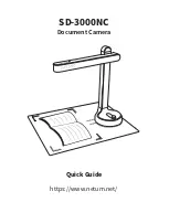
Figure 14 – Exposure mode
The next table specifies the Auto Exposure parameters:
Parameter
Description
Gen<i>Cam name
Type
Possible values
Remarks
Value
Gen<i>Cam name
Gen<i>Cam Category: AcquisitionControl
Exposure Auto Sets the automatic exposure
mode when ExposureMode is
Timed
ExposureAuto
Enumeration
0x00
Off
0x01
Continuous
0x02
Once
Desired
Brightness Level
Image total Brightness Level
DesiredBrightnessLevel
Float
Range: 1 to
(2^bitness – 2)
Exposure Auto
Min Time
Sets the Auto Exposure
minimal time
ExposureAutoMinTime
Float
Range: 1 to Auto
Exposure Max
Time
Exposure Auto
Max Time
Sets the Auto Exposure
maximum time
ExposureAutoMaxTime
Float
Range: Auto
Exposure Min
Time to
Maximum
Exposure Time
Auto Exposure
Filter Ratio
Sets the Auto Exposure filter
effective ratio
ExposureAutoFilterRatio
Range: 0 to 1
Table 11 – Exposure Auto control
10.2
Auto Gain Mode
When operating in this mode, the camera tries to reach the desired brightness level of the picture by adjusting
Analog Gain Level. Steps to set Auto Gain Mode:
1.
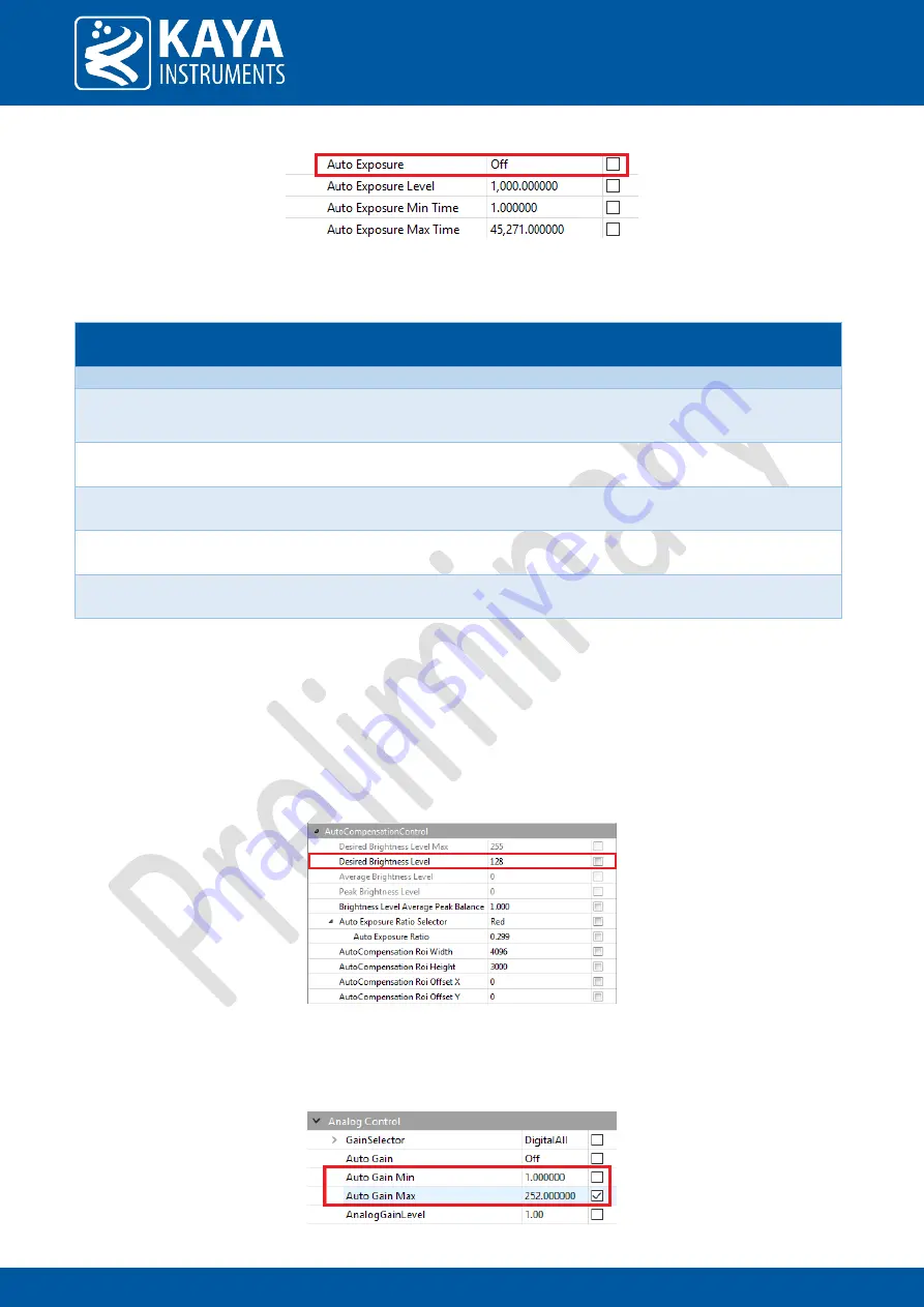
Define Desired Brightness Level
Figure 15 – Brightness Level
2.
Define Auto Gain Minimum and Maximum Gain. These parameters define the limits for analog gain
adjustment. By default, these values will be set to maximum and minimum possible values.
Figure 16 – Auto Gain values