


LINK
net
™
!
USER MANUAL
DCM000000008
Printed: 00.03.22,09:08
Revision Date:3/22/00
3
Congratulations on your purchase of the
LINK
net
™
platform.
Successful operation of the LINK
net
™ in any installation depends upon sound
system design. Service personnel should be aware that most problems experienced
with LINK
net
™ systems are due to failures or inadequacies in equipment outside the
LINK
net
™ platform.
This manual pertains to the LINK
net
™ Platform. It describes how the user should
install, set-up and use the LINK
net
™ Card-cage, Power Supply Module, and Plug in
RF and Controller modules, for proper operation and safety.
The scope of this manual is generally limited to the LINK
net
™ circuitry itself; no
attempt is made to thoroughly discuss all aspects of system or applications design.
KAVAL TELECOM INC.
would be pleased to discuss the engineering aspects of
LINK
net
™ installations and can undertake overall LINK
net
™ system design and
installation.
The LINK
net
™ encompasses the functionality of most of KAVAL TELECOM INC.’s
current electronic product line. All OFR and BDA products are harmonized into a
single modular and adaptable system. The intention is to incorporate the
functionality of most or all of KAVAL TELECOM INC.’s product line into a single
modular family. Newer technology allows implementation of additional features such
as Digital Control, Self-alignment, and Extensive Diagnostics, which make the
modules in this new generation of products more capable than their predecessors.
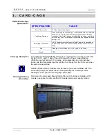
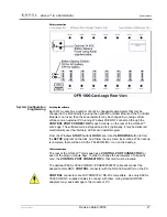
The product is made up of at least one Card-cage, RF Modules, and a Power
Supply. The Modules in the Card-cage interconnect via a back plane that supplies
power and digital control signals.
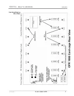
A single Card-cage can be mounted into a 6 unit standard EIA 19 inch rack, with
multiple Card-cages interconnected using a Card-cage Interconnect Harness.
An optional Control Module may be used to program and monitor the independent
RF Modules. By daisy chaining Card-cages together, a single control module can
be used to run up to 110
RF Modules
in a single, integrated, system.
2 . I N T R O D U C T I O N
Document Scope
What Is The
LINK
net
™ Platform?


