background image


Operating Manual 


20 

Original Operating Manual


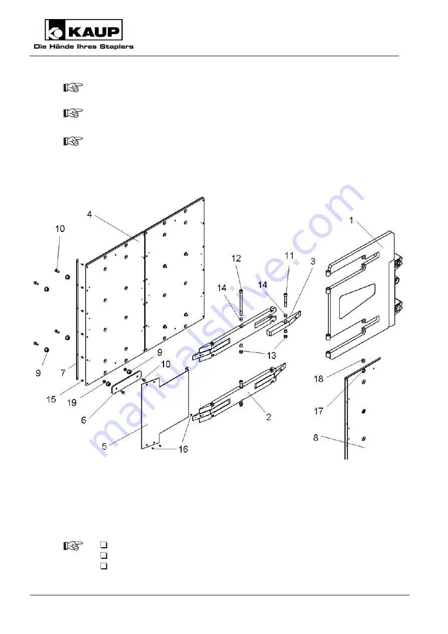
Renew defective wear-off bars (7) by removing the screws (15) and replacing the wear-
off bar (7). Refit the screws again (15). 


Renew the worn bushes (14) in the swing arm (1) by removing the nuts (13) and 
screws (12). Replace the bushes (14). Refit the nuts (13) and screws (12) again. 


Ensure that all plugs (18) are put back into the open borings (17) in the pressure plate 
(4). 


6.3.5  Clamping arms right and left, model T 414-2L 


After 50h / every 500h thereafter 


Check: 


Screws (10) on the rocker arms (3). 


Screws (12) and nuts (13) on the rocker arms (2). 


Screws (11) and nuts (13) on the rocker arms (3). 

Summary of Contents for T 413GT

Page 1: ...appliances 1 arm swivelling one arm fix T403GT 1L Telescopic Appliance Clamp without sideshift and arms with rubber covering for white appliances 1 arm swivelling one arm fix T414GT 1L Telescopic Appliance Clamp with sideshift and arms with rubber covering for white appliances both arms swivelling T404GT 1L Telescopic Appliance Clamp without sideshift and arms with rubber covering for white applia...

Page 2: ...nty claims based on defects 5 1 7 Limits of applicable use 5 2 Safety aspects 6 3 Design 7 3 1 Clamp with mounting 7 3 2 Appliance clamp arms 8 3 3 Proper use of the equipment 9 3 4 Improper use 9 4 Installation and checking out 9 4 1 Installation 9 4 2 Checking out 11 4 2 1 Bleeding the hydraulic system 11 4 2 2 Adjustment after putting into service 11 5 Operation 13 5 1 General 13 5 2 Load handl...

Page 3: ...25 9 Transport 25 10 Decommissioning and storage 26 11 Spare parts list not part of the Operating Manual 26 12 EC Declaration of Conformity Summary 26 Our service department in Aschaffenburg will be happy to answer your technical questions and to provide additional support Technical Support 0049 0 6021 865 395 0049 0 6021 865 284 0049 0 6021 865 352 Orders for spare parts Domestic 0049 0 6021 8652...

Page 4: ... following symbols are used in this operating manual to highlight details of special importance Identifies details relating to do s and don ts for the purpose of avoiding injury and property damage Specific details relating to the efficient use of the attachment and other advice Lists are denoted by a shadowed box Steps to be performed by the operator are denoted by a black dot 1 In illustrations ...

Page 5: ...onents Inappropriate installation maintenance inspection and servicing Assignment of unqualified or non authorised personnel Claims raised by third parties 1 7 Limits of applicable use KAUP attachments are intended for use under the following climatic conditions Average ambient temperature for continuous operation 25 C Allowable maximum ambient temperature short term up to 1h 40 C Allowable minimu...

Page 6: ...a safe distance away from moving reciprocating or rotating parts of the attachment to avoid danger of crushing pinching or entanglement Notify the responsible department person immediately of changes and faults in operation of the attachment that affect safety The attachment shall be shut down Use aids to vision e g mirrors camera etc where goods being transported obstruct vision Only allow work o...

Page 7: ...ounted in the slides 2 onto which clamp arms see Chapter 3 2 are welded or mounted adjustably Cylinders 6 move the slide 2 in the clamping body 1 and cylinders 7 also move the clamping arms attached to the guide profiles 5 in the slide 2 Sideshift components 8 9 or hooks 10 11 are optionally attached to the clamp body 1 A stop plate 12 prevents damage of the transported goods when closing the clam...

Page 8: ... floating mounting The right arm of the 2 3T413GT 1L model consists of guide profiles 1 and an arm 4 in a box design Both arms are equipped with adjustable pre load Both arms of the 2 3T414GT 1L model consist of guide profiles 1 arm brackets 2 and pressure plates 5 which have floating mountings Both arms are equipped with adjustable pre load The arm pressure plates are glued or bolted to the rubbe...

Page 9: ...4 Installation and checking out 4 1 Installation Installation and commissioning should be performed by qualified and authorised personnel only Pay attention to a sufficient load carrying capacity of the lifting means The following are examples of preferred lifting means Capacity 250 kg M16 1200 kg M16 2000 kg M16 Part no 9710160008 0360010201 0360010301 Exceeding the allowable load capacity and lo...

Page 10: ...ucks equipped with attachments which hold the load by power e g paper clamp shall feature control s with a secondary action to prevent unintentional release of the load Also take note in this respect of the operating instruction of the lift truck Before initial operation check the functions and the identification of the attachment with the movement directions of the operating elements operating le...

Page 11: ... 2 1 Bleeding the hydraulic system Start the lift truck Move the sideshifter repeatedly in both directions to maximum extent Repeatedly cycle the clamp from the fully open to the fully closed position Inspect the hydraulic connections for leakage 4 2 2 Adjustment after putting into service The hydraulic system is under pressure During work on hydraulic components oil spurting out can cause injurie...

Page 12: ...miting valve Attachments are adjusted ex factory to a pressure of 160 bar A change in pressure is necessary only if the load slips or is damaged Make the settings in the numerical sequence and in the direction of the arrows The pressure indication on the manometer gauge drops after clamping This is not a malfunction of the attachment being caused by the installation of a transmission ...

Page 13: ...hment as stated on the rating plate This figure always represents the load carried by two or more arms 5 2 Load handling Set the forks as wide apart as possible for the load to be carried Position the mast vertically and take up the load parallel to the floor Always transport pallets boxes and containers using both forks Drive the attachment up to the load to maximum extent Raise the load about 30...

Page 14: ...they can result in a risk of accident The EC Declaration of Conformity by the manufacturer becomes invalid and you assume full responsibility in the case of accident Use only original spare parts from the manufacturer The hydraulic system is under pressure During work on hydraulic components oil spurting out can cause injuries Unload the system in accordance with the operating instructions of the ...

Page 15: ...idated by a significant modification of the attachment Modifications to the attachment may only be made with prior approval by the manufacturer 6 3 Schedule for routine maintenance and lubricants Lubricants approved and recommended by KAUP Greases Note Lithium soap grease NLGI Class 2 e g Avialith 2 Designation DIN51825 K 2 K 30 Complex soap grease NLGI Class 2 e g Turmogrease Gel M 5 Foundry qual...

Page 16: ...Operating Manual 16 Original Operating Manual 6 3 1 Clamp 6 3 2 Mounting with or without sideshift ...

Page 17: ...s 19 bolt 14 Supporting rollers 24 As necessary Renew worn sliders 19 by removing the hooks 23 Remove the complete clamp body 8 in the reverse order to that described in section 4 1 Replace the sliders 19 During installation pay close attention that the sliders 19 are seated correctly Then fit the clamp as described in section 4 1 Replace worn sliding pieces 3 by removing nut 6 from each cylinder ...

Page 18: ...on the lift truck Remove the bolts 25 in the hooks 23 remove the defective supporting rollers 24 and replace them with new ones Remount the clamp body 8 in the reverse order After installing or removing a cylinder 7 10 always check the clearance between the cylinder mount 17 and nut 6 11 of the cylinder 7 10 Cylinders are installed with axial clearance of 1 5 to 2 mm Renew defective pins 14 by rem...

Page 19: ...over sheets 5 Replace loose or damaged screws Torque the screws as specified in Chapter 6 1 General Every 200h Check wear on Coating 8 Wear off bar 6 7 Bushes 14 As necessary Renew the worn covering 8 or wear off bar 6 by removing the cover plate 5 and screws 16 Remove the screw 10 and bushes 9 Take off the pressure plate 4 to the side Replace the covering 8 or wear off bar 6 If the wear is only s...

Page 20: ...ing arm 1 by removing the nuts 13 and screws 12 Replace the bushes 14 Refit the nuts 13 and screws 12 again Ensure that all plugs 18 are put back into the open borings 17 in the pressure plate 4 6 3 5 Clamping arms right and left model T 414 2L After 50h every 500h thereafter Check Screws 10 on the rocker arms 3 Screws 12 and nuts 13 on the rocker arms 2 Screws 11 and nuts 13 on the rocker arms 3 ...

Page 21: ...covering 8 or wear off bar 6 If the wear is only slight you can also turn the pressure plate 4 and wear off bar 6 through 180 Refit all parts again in the reverse order Renew defective wear off bars 7 by removing the screws 15 and replacing the wear off bar 7 Refit the screws again 15 Replace warn bushings 14 in the rocker arms 2 by removing the screws 12 and nuts 13 Remove the pressure plate 4 fr...

Page 22: ...e profile 3 and retainer 2 of the arm If required changing the arm pre load Open the clamp so that the rear of the arms 1 is freely accessible Loosen the bolts 4 Change the arm pre load by adjusting the bolt 5 Movement in the direction reduces the pre load Movement in the direction increases the pre load Adjust the arms on both profiles 3 Retighten the bolts 4 after successfully adjusting them ...

Page 23: ...y by quality department 2 Before putting into operation carefully read and take note of the operating and security instructions 0100016401 3 Never reach into the unit as long as parts could still be moving due to the danger of squashing or shearing 0100016601 4 Use suspension point 0100015001 5 koxxxxxx KAUP order number without engraved in the material ...

Page 24: ...olding Pressure too low Increase the pressure from the lift truck Pressure too low on pressure relief valve Increase pressure on the pressure relief valve Cylinders have internal leaks Replace sealing kits Clearance Carriage has too much clearance Slider is worn Replace sliders Carriage tilts at outer limit Slider is worn Replace sliders Carriage rubbing against guide section Slider is worn Replac...

Page 25: ... kit defective Replace sealing kit Piston rod scored Replace piston rod and sealing kit Solenoid valve Not functioning Solenoid coil defective Replace solenoid coil No power to the magnet Inspect power cable and connections Legend FFZ lift truck DBV Pressure relief valve WE Drossel elbow type screwed throttle 8 Disposal Prevent environmental damage by disposing of the following items properly in a...

Page 26: ...arts list not part of the Operating Manual 12 EC Declaration of Conformity Summary KAUP GMBH Co KG Braunstraße 17 D 63741 Aschaffenburg we hereby declare that the machinery Model Telescopic Appliance Clamp Type T413GT T403GT T413GT 1L T403GT 1L T414GT 1L T404GT 1L T 414GT 2L T404GT 2L conforms to the latest valid version of the Machinery Directive 2006 42 EG The person authorised to compile the te...

Reviews: