background image

19

c.4 Lighting the boiler for the first time

A skilled technician must perform the first lighting; otherwise, the guarantee will expire. 

c.5 Activating the boiler

When the pellet tank is filled for the first time, you must remember that the screw tube, which feeds 
the  grate,  is  completely  empty;  therefore,  when  you  light  the  boiler  for  the  first  time  you  must 
manually insert the pellets and light the boiler. 

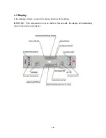
Press the key n. 4 “ON/OFF” until the message “FAN CARD” appears on the display. 

While lighting, the boiler begins pre-heating the resistance for approximately 1 minute.

After the pre-heating, the message “LOAD WOOD” appears; this means that the screw is loading 
the pellets at a speed, which is defined by the technical settings (which can be modified). 

The  fuel  loaded  in  the  grate  meets  the  incandescent  resistance  and  will  burn,  provoking  the 
beginning of the combustion. 

When the switchboard infers through the probe that the temperature is high enough, the boiler is 
brought to the control mode, which will make the message “FIRE ON” appear on the display. In the 
while, the pellet supply is increased to raise the temperature even higher, with a defined gradient 
(approximately 3°C per minute). 

When  the  pellets  inside  the  grate  are  completely  burned,  the  boiler  proceeds  in  its  normal 
functioning. 

The water pressure for the lighting of the boiler goes from o.5 to 1.5bars. It is possible to display 
the internal pressure of to the system by pressing the key n. 2 for a few seconds. 

c.6 Room temperature setting

The boiler is equipped of a thermostat with a room temperature survey probe, which is located on 
the back. Its use permits to stabilize and maintain the temperature in the room where it is situated.  

To  modify  the  room  temperature  it  is  sufficient  to  push  the  key  n.  3  “SET”  for  a  while,  then  to 
regulate the increase and decrease of the temperature with the keys n. 1 and 2. 

IMPORTANT:

WHEN  THE  ROOM  TEMPERATURE  IS  REACHED,  THE  BOILER  AUTOMATICALLY 
MODULATES  THE  PELLET  SUPPLYING  BY  USING  THE  NECESSARY  FUEL  TO  MAINTAIN 
THE SET TEMPERATURE (“RIS” MODE).

Summary of Contents for KK IDRO

Page 1: ...PELLET BOILER KK IDRO OPERATING AND MAINTENANCE HANDBOOK...

Page 2: ...u may know and use the product at its best as well as ordinarily upkeep it Our authorized technical service remains at Your complete disposal for any necessity Best regards Karmek S R L PLEASE NOTE Ka...

Page 3: ...Installing the combustion air inlet pipe b 6 Connecting to the power supply b 7 Connecting to the waterworks C OPERATING INSTRUCTIONS c 1 Initial warnings c 2 Presentation c 3 Display c 4 Lighting the...

Page 4: ...ORDINARY CLEANING AND MAINTENANCE f 1 Cleaning and maintenance by the customer f 2 Periodic maintenance by the Assistance Center G ALARMS DISPLAYING g 1 Fumes temperature probe alarm g 2 Unsuccessful...

Page 5: ...the boiler so to check the efficiency of the flue draught before and after the combustion work of the boiler The boiler consumes as much air as it is necessary for the combustion it is thus advisable...

Page 6: ...oke severe burns Do not perform interventions on the boiler apart from those expected for a regular functioning or suggested in this handbook in order to solve slight problems In any case always unplu...

Page 7: ...austed gas temperature at nominal thermic power 300 3 C at reduced thermic power 205 4 C Minimum requirements for the chimney s draught at nominal thermic power 12Pa Minimum requirements for the chimn...

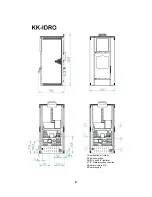
Page 8: ...8 1 Combustion air intake 2 Flue connection 3 H2O Lock 3 4 radiator 4 1 2 Waterworks connection 5 Radiator return 3 4 6 Power supply...

Page 9: ...ity plate is positioned on the back of the boiler and it reports the following data commercial brand supply tension serial number absorbed electric supply model nominal frequency thermal power minimum...

Page 10: ...and density Kg dm 1 0 1 4 The boiler is built to burn not resinous preferably beech wood pellets therefore using pellets whose characteristics are different from the ones listed above reduces its eff...

Page 11: ...orks in the proper slots of the wooden packing In order to position the boiler inside a room a good general rule is to lay the boiler on the floor gently with maximum caution and avoiding any violent...

Page 12: ...led FIG 2 INSTALLATION WITH AN EXISTING FLUE Flue gas outlet 100 Reach the existing flue horizontally making sure that it presents a minimum section of 200cm and an easy to inspect base for its annual...

Page 13: ...13 100 100...

Page 14: ...ue b 6 Connecting to the power supply Verify if the electrical system and the mains outlets present the capacity to support the maximum absorption of the boiler which is reported on the plate Make sur...

Page 15: ...15 ELECTRICAL SCHEME...

Page 16: ...ors and other exchangers without any additional components When connecting the boiler with the waterworks you must be make sure that the equipped joints are compatible with those of the system otherwi...

Page 17: ...rogramming The automatic loading and the consistent capacity of the tank allow the pellet boiler to perform automatically for a longer time and they permit a better management of the device If the boi...

Page 18: ...Display In the following scheme we report the various functions of the display IMPORTANT If the temperature is not set within a few seconds the display will automatically return to the previous scree...

Page 19: ...he temperature is high enough the boiler is brought to the control mode which will make the message FIRE ON appear on the display In the while the pellet supply is increased to raise the temperature e...

Page 20: ...ient to push the key n 6 for approximately 2 seconds This operation will immediately restart the working phase ON the complete lighting phase can be spared if the temperature of the fumes is higher th...

Page 21: ...o set UT5 Start program 1 From 00 00 to 23 50 10 step UT6 Stop program 1 From 00 00 to 23 50 10 step UT7 Daily lighting switching off Between on off for 1 to 7 days UT8 Start program 1 From 00 00 to 2...

Page 22: ...key you set or unset the program UT08 UT09 they indicate the starting and stopping time of the Program 2 if the UT01 setting is set on the weekly mode different from OFF UT10 it modifies the weekdays...

Page 23: ...ficiency d 3 Safety thermostat The safety thermostat is situated on the left side of the boiler It operates by switching the boiler off when the maximum threshold of the water temperature is reached T...

Page 24: ...of the water circuit of the boiler and has a total volume of 6 liters d 8 Transducer The pressure transducer surveys the exercise pressure of the system which in normal conditions varies between 1 an...

Page 25: ...lighting of the pellets occurs because of the overheating of the plug and the heating of the air inside the combustion chamber d 14 Pressurestat The pressurestat unsets the functioning of the screw r...

Page 26: ...ipe of the boiler Remove the furnace s internal covering accurately clean and remove the incrustations inside the crucible and its space Clean the fans and check the mechanism of the plays and of the...

Page 27: ...er circuit ALARM PRES g 1 Fumes temperature probe alarm It occurs in case of breakdown or disconnection of the fumes temperature probe The boiler will switch off automatically then check for the wires...

Page 28: ...or substitute the probe g 7 Circuit pressure alarm It occurs when the transducer surveys a pressure lower than 0 7 bars or higher than 1 5 bars The boiler immediately activates the switching off proc...

Page 29: ...are embedded in the chute checking if screw is blocked check the door seal The boiler is blocked Excessive use without cleaning the grate Empty tank Screw without pellets Clean the grate Load the pell...

Page 30: ...e boiler Check if the flue is clean Check the quality of the pellets Contact the authorized assistance center Check the anti wind terminal and or install it if necessary Check if the grate is correctl...

Page 31: ......
Page 32: ...GUARANTEE CONDITIONS AT THE END OF EACH SEASON IT IS OBLIGATORY TO HAVE THE AUTHORIZED ASSISTANCE CENTER PERFORM A GENERAL CLEANING OF THE MODULE OTHERWISE THE GUARANTEE WILL EXPIRE...

Reviews: