


7
6
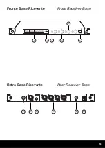
1.
DISPLAY
Vi permetterà di visualizzare le frequenze dei
relativi radiomicrofoni utilizzati
2.
TASTO SET/LOCK
Premendolo avrete la possibilità di settare
manualmente la frequenza o bloccarla.
Una volta entrati in modalità manuale, utilizzate
i tasti IR () e SCAN () per muovervi tra le
frequenze selezionabili
3.
TASTO SCAN / VOL -
Premetelo per avviare la scansione automatica
della frequenza libera da disturbi nell’ambiente.
Premete il tasto per abbassare il volume del
singolo radiomicrofono
4.
TASTO IR / VOL +
Tenendo premuto il tasto entrerete in modalità
“accoppiamento”. Avvicinate il radiomicrofono al
sensore IR (11) della ricevente.
Premete il tasto per alzare il volume del singolo
radiomicrofono
5.
TASTO DI ACCENSIONE
Utilizzatelo per accendere il prodotto. Il relativo
led si accenderà.
6.
ANTENNA
Utilizzatela e regolatela per permettervi un
aggancio migliore alla frequenza desiderata
7.
USCITA XLR MIXATA
Utilizzate questa uscita bilanciata per ottenere il
segnale mixato dei 4 radiomicrofoni
8.
PRESA JACK 6,3mm MIXATA
Utilizzate questa uscita non bilanciata per
ottenere il segnale mixato dei 4 radiomicrofoni
9.
PRESE XLR
Utilizzate queste uscite bilanciate per ottenere il
segnale singolo dei 4 radiomicrofoni
1.
DISPLAY
It shows the frequencies of the operating
wireless microphones.
2.
SET/LOCK BUTTON
Press it to set manually the frequency or lock
it. Once you are in manual mode, use the
keys IR ( ) and SCAN ( ) to scroll through the
selectable frequencies.
3.
SCAN / VOL - BUTTON
Use it to start frequency auto scan, free from
environmental interferences.
Press this button to reduce the volume of the
single microphone.
4.
IR / VOL + BUTTON
Use it to enter pairing “mode”. Put the
wireless microphone near the receiver’s IR
sensor (11).
Press this button to increase the volume of the
single microphone.
5.
ON/OFF SWITCH
Use it to turn on the product. The related led
will light on
6.
ANTENNA
Adjust it for a better performance on the
desired frequency
7.
XLR MIXED OUTPUT
Use this balanced output to obtain the 4
microphones’ mixed signal
8.
MIXED 6,3 mm jack SOCKET
Use this unbalanced output to obtain the 4
microphones’ mixed signal
9.
XLR SOCKETS
Use these balanced outputs to obtain the 4
wireless microphones’ single signal
Funzioni
Functions


