


TECHNICAL REFERENCE & INSTALLATION GUIDE
6
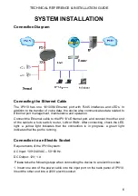
SYSTEM INSTALLATION
ConnectIon Diagram
ConnectIng the Ethernet Cable
The IPV10 has one 10/100M Ethernet port with RJ45 interfaces and LEDs. In
addition to the transfer of voice data, the device also communicates data related to
Ethernet port management, maintenance and operation.
Connect the Ethernet cable to the IPV10's Ethernet port, and connect the other end
of the cable to a hub, switch, router, LAN or WAN. After connecting, check the LED
light: a yellow light indicates that the connection is in progress; a green light
indicates that the port is running.
ConnectIon to an ElectrIc Socket
Requirements of the IPV10 system:
AC Input: 100~240VAC – 50~60 Hz.
DC Output: 12V; 1 A
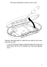
Please take the following steps when connecting the device to an electric socket.
1. Insert one end of the power cable into the input port on the back panel of IPV10.
Insert the other end into a 220V electric socket.


