background image


English 

5.906-507.0 Rev. 00 (08/10)

 11

Î

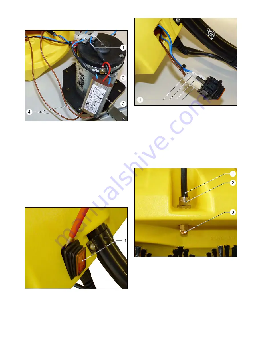
Remove the motor as described in Chapter 5.2.2.

1 Motor connection plug
2 Cable connector screw, noise filter
3 Anti-interference filter
4 Connecting cable, noise filter

Î

Pull the motor connection plug from the motor.

Î

Unscrew the cable connector screw from the noise 
filter on the motor.

Î

Remove the connecting cable from the appliance 
switch/safety switch.

Î

Install the new noise filter in reverse order.

Î

Install the motor as described in Chapter 5.2.2.

The removal of the toothed drive wheel is described 
in the Chapter 5.5.2.

1 Power switch

Î

Push out the appliance switch from the casing us-
ing a screwdriver.

1 Connecting cable (4x), appliance switch

Î

Remove the appliance switch from the casing.

Note
In order to avoid failures, remember the plug connec-
tions of the different connecting cables on the appli-
ance switch.

Î

Remove all four connecting cable from the appli-
ance switch.

Î

Replace the appliance switch and install it in re-
verse order.

1 Spray hose
2 Lock nut
3 Spray nozzle

Î

Place the PW 30/1 on its back.

Î

Unscrew the knurled nut.

Î

Pull the spray hose from the spray nozzle.

5.2.3 Replace the interference filter

5.2.4 Replace toothed drive wheel

5.2.5 Replace appliance switch

5.2.6 Replace the spray hose

Summary of Contents for PW 20

Page 1: ...English 5 906 507 0 Rev 00 08 10 1 PW 20 PW 30 1 Service Manual ...

Page 2: ...safety switch 7 4 2 PW 30 1 5 5 2 1 Replacing the brush roller 7 5 2 2 Replace the motor 9 5 2 3 Replace the interference filter 11 5 2 4 Replace toothed drive wheel 11 5 2 5 Replace appliance switch 11 5 2 6 Replace the spray hose 11 5 2 7 Replace the spray nozzle 12 5 2 8 Replace the spray valve 12 5 2 9 Replacing the mains cable 13 5 2 10 Replace the running roller 13 5 2 11 Reset the safety sw...

Page 3: ...xts and diagrams as well as third party access to this information is permitted only with the explicit permission of the company Alfred Kärcher GmbH Co KG P O Box 160 D 71349 Winnenden www kaercher com Danger Immediate danger that can cause severe injury or even death 몇 Warning Possible hazardous situation that could lead to se vere injury or even death Caution Possible hazardous situation that co...

Page 4: ...y hose 4 Power switch 5 Running roller 6 Safety switch 7 Mount for swivel arm 8 Valve handle 9 Suction pipe 10 Carrying handle 1 Brush roller 2 Spray nozzles 3 Covering plate 4 Brush roller drive 5 Running roller 4 Parts of the system 4 1 PW 20 9 8 10 4 3 6 7 1 5 2 ...

Page 5: ...0 5 1 Power switch 2 Holding plate 3 Running roller 4 Safety switch 5 Hood 6 Casing 7 Spray hose 8 Valve handle 9 Suction pipe 10 Power cord 1 Running roller 2 Brush roller 3 Spray hose 4 Spray nozzle 4 2 PW 30 1 10 5 1 4 9 8 2 6 3 7 ...

Page 6: ...d belt Î Remove the brush Î Assembly of the brush in reverse sequence 1 Brush motor 2 Fastening screw for brush motor 3 Drive pinion 4 Mount for swivel arm 5 Gear belt 6 Cover 7 Spray nozzles 8 Fastening screws for cover 9 Nozzle tube Î Place the PW 20 on its back and swivel up the brush roller Î Unscrew and withdraw both bolts on the front of the brush Î Remove the toothed belt Î Remove the brush...

Page 7: ...new mains cable in reverse sequence Î Remove the connecting cable of the noise filter on the brush motor and unscrew it from the terminal strip Î Replace the interference filter Î Connect the new noise filter Î Remove the connecting cable from the appliance switch safety switch Î Replace the appliance switch safety switch Î Connect the appliance switch safety switch 1 Brush roller 2 Brush roller c...

Page 8: ...e wheel Î Remove the toothed belts from the toothed wheels Î Pull the brush roller out of the brush head Î Install the new brush roller in reverse order Î Insert the brush roller into the guide bore of the brush roller cover plate 1 Elongated hole 2 Toothed wheel brush roller Î Watch for the correct seating of the threaded sleeve in the elongated hole when installing the brush roller Î Screw in th...

Page 9: ...able tools Î Screw in the toothed belt cover 1 Toothed belt cover 2 Fastening screws Î Unscrew locking screws Î Remove cover Î Remove the fastening screw from the brush roller 1 Toothed wheel brush roller 2 Gear belt 3 Toothed drive wheel Î Remove the toothed belts from the toothed wheels Î Pull the brush roller out of the brush head 5 2 2 Replace the motor ...

Page 10: ... cable connector screw from the noise filter on the motor 1 Protective cap 2x 2 Motor fastening screws 2x Î Remove the protective caps from the motor fas tening screws Î Unscrew the motor fastening screws 1 Toothed drive wheel 2 Grub screw 2x Î Loosen both grub screws from the toothed drive wheel Î Pull the toothed drive wheel for the motor axle Î Separate the motor from the motor support Î Replac...

Page 11: ...eel is described in the Chapter 5 5 2 1 Power switch Î Push out the appliance switch from the casing us ing a screwdriver 1 Connecting cable 4x appliance switch Î Remove the appliance switch from the casing Note In order to avoid failures remember the plug connec tions of the different connecting cables on the appli ance switch Î Remove all four connecting cable from the appli ance switch Î Replac...

Page 12: ...er 5 2 6 1 Hexagonal SW 13 2 Spray nozzle SW 10 Î Hold the hexagonal with the wrench SW 13 Î Unscrew the spray nozzle using a wrench SW 10 Î Replace the spray nozzle and install it in reverse order Î Pull the spray hose from the spray valve as de scribed in Chapter 5 2 6 1 Spray hose 2 Lock nut 3 Fastening screws spray valve 4 Spray valve 5 Connection hose Î Unscrew the fastening screw from the sp...

Page 13: ... back Î Loosen the fastening screw Î Replace the running roller and install it in reverse order The safety switch is an overload protector switch and is located underneath the protective cap arrow If the brush roller is blocked the safety switch will switch off the appliance In order to restart the appliance reset the safety switch as follows Î Unscrew the protective cap from the casing using a su...

Page 14: ...e if there are impurities and re move blocking objects if any Î Remove the safety cap and press the safety switch by means of a screwdriver Î Reinstall the safety cap The status of the attached circuit diagram represents the creation date of the service manual This circuit diagram is not updated When working on the device please always use the current circuit diagram in Kärcher Inside There are no...

Page 15: ...English 5 906 507 0 Rev 00 08 10 15 9 Circuit diagram 9 1 PW 20 ...

Page 16: ...16 English 5 906 507 0 Rev 00 08 10 9 2 PW 30 1 ...

Reviews: