background image

9.801-811.0 • Rev. 06/17


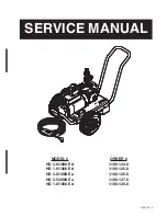
PRESSURE WASHER   

SERVICE MANUAL

4

INTRODUCTION & IMPORTANT SAFETY INFORMATION

Thank you for purchasing this Pressure Washer.
We  reserve  the  right  to  make  changes  at  any  time 
without incurring any obligation.

Owner/User Responsibility:

The owner and/or user must have an understanding of 
the manufacturer’s operating instructions and warnings 
before using this pressure washer. Warning information 
should be emphasized and understood. If the operator 
is not fluent in English, the manufacturer’s instructions 
and  warnings  shall  be  read  to  and  discussed  with 
the operator in the operator’s native language by the 
purchaser/owner, making sure that the operator com

-

prehends its contents.
Owner and/or user must study and maintain for future 
reference the manufacturers’ instructions.
The  operator  must  know  how  to  stop  the  machine 
quickly  and  understand  the  operation  of  all  controls. 
Never  permit  anyone  to  operate  the  engine  without 
proper instructions.

SAVE THESE INSTRUCTIONS 
This manual should be considered a permanent 

part of the machine and should remain with it if 

machine is resold.
When ordering parts, please specify model and 

serial number. Use only identical replacement parts.
This machine is to be used only by trained operators.

IMPORTANT SAFETY 

INFORMATION

READ OPERATOR’S 

MANUAL THOROUGHLY 

PRIOR TO USE.

WARNING: To reduce the risk of 

injury, read operating instruc-
tions carefully before using.

  1.  Read  the  owner's  manual 

thoroughly.  Failure  to  follow 
instructions could cause mal

-

function  of  the  machine  and 
result in death, serious bodily 
injury and/or property damage.


2.  Know how to stop the ma

-

chine  and  bleed  pressure  quickly.  Be  thoroughly 
familiar with the controls.

  3.  Stay alert — watch what you are doing.
  4.  All  installations  must  comply  with  local  codes. 

Contact your electrician, plumber, utility company 
or the selling distributor for specific details. If your 
machine is rated 250 volts or less, single phase will 
be provided with a ground fault circuit interrupter 
(GFCI). If rated more than 250 volts, or more than 
single phase this product should only be connected 
to a power supply receptacle protected by a GFCI.

DANGER: Improper connection of the equipment-
grounding conductor can result in a risk of elec-
trocution. Check with a qualified electrician or 
service personnel if you are in doubt as to whether 
the outlet is properly grounded. Do not modify the 
plug provided with the product - if it will not fit the 
outlet, have a proper outlet installed by a qualified 
electrician. Do not use any type of adaptor with 
this product

WARNING

KEEP WATER 

SPRAY AWAY FROM 

ELECTRICAL WIRING.

WARNING: Keep wand, hose, and 

water spray away from electric 
wiring or fatal electric shock may 
result.

5.    To protect the operator from  
 

electrical shock, the machine  


must be electrically grounded. 


It  is  the  responsibility  of  the  


owner to connect this machine 

to a UL grounded receptacle of proper voltage and 
amperage ratings. Do not spray water on or near 
electrical components. Do not touch machine with 
wet hands or while standing in water. Always dis

-

connect power before servicing.

RISK OF EXPLOSION: 

DO NOT SPRAY  

FLAMMABLE LIQUIDS.

WARNING

WARNING: Flammable liquids 

can create fumes which can ig-
nite, causing property damage 
or severe injury.
WARNING: Risk of explosion — 
Do not spray flammable liquids.


6. Do not allow acids, caustic 

or abrasive fluids to pass through the pump.

  7.  Never  run  pump  dry  or  leave  spray  gun  closed 

longer than 1-2 minutes.

  8.  Keep operating area clear of all persons.

WARNING


USE PROTECTIVE  

EYE WEAR 

AND CLOTHING  

WHEN OPERATING 

THIS EQUIPMENT.

WARNING: High pressure spray 

can cause paint chips or other 
particles to become airborne 
and fly at high speeds. To avoid 
personal injury, eye, hand and 
foot safety devices must be 
worn.

  9.  Eye,  hand,  and  foot  pro

-

tection  must  be  worn  when 
u s i n g   t h i s   e q u i p m e n t .

Summary of Contents for HD 2.0/1000 Ed

Page 1: ...9 801 811 0 SERVICE MANUAL MODEL ORDER HD 2 0 1000 Ed 1 106 124 0 HD 1 9 1300 Ed 1 106 125 0 HD 3 0 1000 Ea 1 106 126 0 HD 3 5 2000 Ea HD 1 8 1300 Ed 1 106 127 0 1 106 128 0...

Page 2: ......

Page 3: ...10 LF2030S Series Pump Exploded view and part s list 11 12 LF3530F Series Pump Exploded view and part s list 13 14 LF2030F Series Pump Exploded view and part s list 15 16 LF2830S Series Pump Exploded...

Page 4: ...ber utility company or the selling distributor for specific details If your machine is rated 250 volts or less single phase will be provided with a ground fault circuit interrupter GFCI If rated more...

Page 5: ...G Protect machine from freezing 13 To keep machine in best operating conditions it is important you protect machine from freezing Failure to protect machine from freezing could cause malfunction of th...

Page 6: ...27 2 3 18 7 6 3 39 5 37 10 9 8 15 14 23 22 4 16 51 53 1 For Detail See Pump Assy 20 21 19 17 38 38 39 47 54 40 50 40 56 52 57 43 47 55 55 46 36 48 48 46 42 42 39 43 44 44 45 45 24 23 49 38 39 17 55 54...

Page 7: ...2 1 3000 3450RPM HD 1 9 1300 Ed HD 1 8 1300 Ed 1 8 754 761 0 Pump Leuco LF2030S 2 1 3000 1725RPM HD 2 0 1000 Ed 1 8 754 763 0 Pump Leuco LF2830S 2 8 3000 1725RPM HD 3 0 1000 Ea 1 8 754 764 0 Pump Leuc...

Page 8: ...NPT 23 45D HD 1 8 1300 Ea 2 9 802 518 0 Strain Relief LT STR 3 4 NPT 49 71D HD 3 5 2000 Ea HD3 0 1000 Ea HD1 9 1300 Ed 1 44 8 900 840 0 Label Remote Switch Home Depot HD 1 8 1300 Ea 1 45 9 802 451 0 S...

Page 9: ...3450RPM HD 3 5 2000 Ea 1 2 8 707 256 0 Pump protector 1 2 1 3 8 706 168 0 Elbow 3 8 NPT p n tf3529x6 Steel 1 4 8 750 299 0 Unloader Vrt3 8 GPM 4500 psi 1 5 8 706 207 0 Elbow 3 8 Street 90 deg Steel 1...

Page 10: ...56 0 Pump protector 1 2 1 3 8 706 207 0 ELBOW 3 8 STREET 90 DEG STEEL 1 4 9 802 362 0 UNLOADER PA 8 3650 VB8 W SWITCH 1 5 9 802 171 0 Coupler 3 8 Clug Male Steel zinc 1 6 8 706 944 0 Hose Barb 3 8 bar...

Page 11: ...ollow 1 33 8 754 219 0 Oil Dipstick 1 34 8 754 840 0 Bearing Needle 1 35 8 754 826 0 Seal Crankshaft 1 36 8 754 844 0 Flange Motor 1 37 9 803 210 0 Washer 10 38 8 752 824 0 Screw 6 mm 4 ITEM PART NO D...

Page 12: ...od 6 47 8 754 847 0 O ring 2 62 X 111 62 1 48 8 754 842 0 Cover Crankcase 1 49 9 803 906 0 O ring 1 78 X 14 1 50 9 803 202 0 Sight Glass G3 4 1 REPAIR KIT NUMBER 8 754 860 0 8 754 856 0 8 754 861 0 8...

Page 13: ...t 5 8 Hollow 1 33 8 754 219 0 Oil Dipstick 1 34 8 754 840 0 Bearing Needle 1 35 8 754 826 0 Seal Crankshaft 1 36 8 754 844 0 Flange Motor 1 37 9 803 210 0 Washer 10 38 8 752 824 0 Screw 6 mm 4 ITEM PA...

Page 14: ...g Rod Pin 3 45 9 803 966 0 Connecting Rod 3 46 8 933 020 0 Screw Connecting Rod 6 47 8 754 847 0 O ring 2 62 X 111 62 1 48 8 754 842 0 Cover Crankcase 1 49 9 803 906 0 O ring 1 78 X 14 1 50 9 803 202...

Page 15: ...0 Shaft 5 8 Hollow 3530F 1 33 8 754 219 0 Oil Dipstick 1 34 8 754 840 0 Bearing Needle 1 35 8 754 826 0 Seal Crankshaft 1 36 8 754 844 0 Flange Motor 1 37 9 803 210 0 Washer 10 38 8 752 824 0 Screw 6...

Page 16: ...Rod Pin 3 45 9 803 966 0 Connecting Rod 3 46 8 933 020 0 Screw Connecting Rod 6 47 8 754 847 0 O ring 2 62 X 111 62 1 48 8 754 842 0 Cover Crankcase 1 49 9 803 906 0 O ring 1 78 X 14 1 50 9 803 202 0...

Page 17: ...13 See Kit Below Valve Assembly 6 14 9 803 948 0 O ring 1 78 X 18 77 6 15 9 803 949 0 Valve Plug 6 16 8 754 851 0 Plug Brass G1 4 1 17 8 754 845 0 Washer Copper G1 4 1 18 8 754 854 0 Bolt Manifold M1...

Page 18: ...KIT WILL SERVICE 3 3 1 1 1 1 6 3 LF2830S SERIES PUMP EXPLODED VIEW PARTS LIST ITEM PART NO DESCRIPTION QTY 36 8 754 844 0 Flange Motor 1 37 9 803 210 0 Washer 10 38 8 752 824 0 Screw 6 mm 4 39 8 754...

Page 19: ...e 6 Remove the adjustment knob Item 18 tighten the lower nut Item 15 tightly against the upper nut Item 15 Reattach adjustment knob Item 18 and screw down until contact is made with the nuts Items 15...

Page 20: ...9 801 811 0 Rev 06 17 PRESSURE WASHER SERVICE MANUAL 20 WIRING DIAGRAM 1 106 124 0 HD 2 0 1000 Ed...

Page 21: ...9 801 811 0 Rev 06 17 21 PRESSURE WASHER SERVICE MANUAL WIRING DIAGRAM 1 3 2 4 NTROL SWITCH W ALL WIRES BLACK UNLESS NOTED G GREEN W WHITE FOR 1 106 125 0 HD 1 9 1300 Ed FOR 1 106 126 0 HD 3 0 1000 Ea...

Page 22: ...7 PRESSURE WASHER SERVICE MANUAL 22 WIRING DIAGRAM MOTOR PUMP 4 CONTROL SWITCH 2 G Y 3 1 G Y G Y G Y 220V 1PH INCOMING POWER WIRE COLOR LEGEND ALL WIRES BLACK UNLESS NOTED G Y GREEN YELLOW FOR 1 106 1...

Page 23: ...PUMP MOTOR RESET IN 5 2 3 6 7 N C TIMER PRESSURE SWITCH 120V GFCI G G G W W W C NC NO 1 2 6 120V COIL STARTER MAGNETIC TIMER 120V B B B T1 13 G B T2 N O B 14 L1 L2 W W W W G OUT WIRE COLOR LEGEND ALL...

Page 24: ...e if necessary Foreign matter in valves Check and clean if necessary Worn bearings Check and replace if necessary Excessive temperature of water Reduce to below 160o F PRESENCE OF WATER IN PUMP OIL Oi...

Page 25: ...life of your pressure washer Perform maintenance more often under severe conditions OIL CHANGE RECORD Check pump oil and engine oil level before first use of your new pressure washer Date Oil Changed...

Page 26: ...KNA Inc 4555 Airport Way Denver CO 80239 Form 9 801 811 0 Rev 06 17 Printed in U S A or Mexico...

Reviews: