background image

Page 7/10

International Service Information

International Service Information

June 24th, 1999

HD 1050 B

New Unit Information

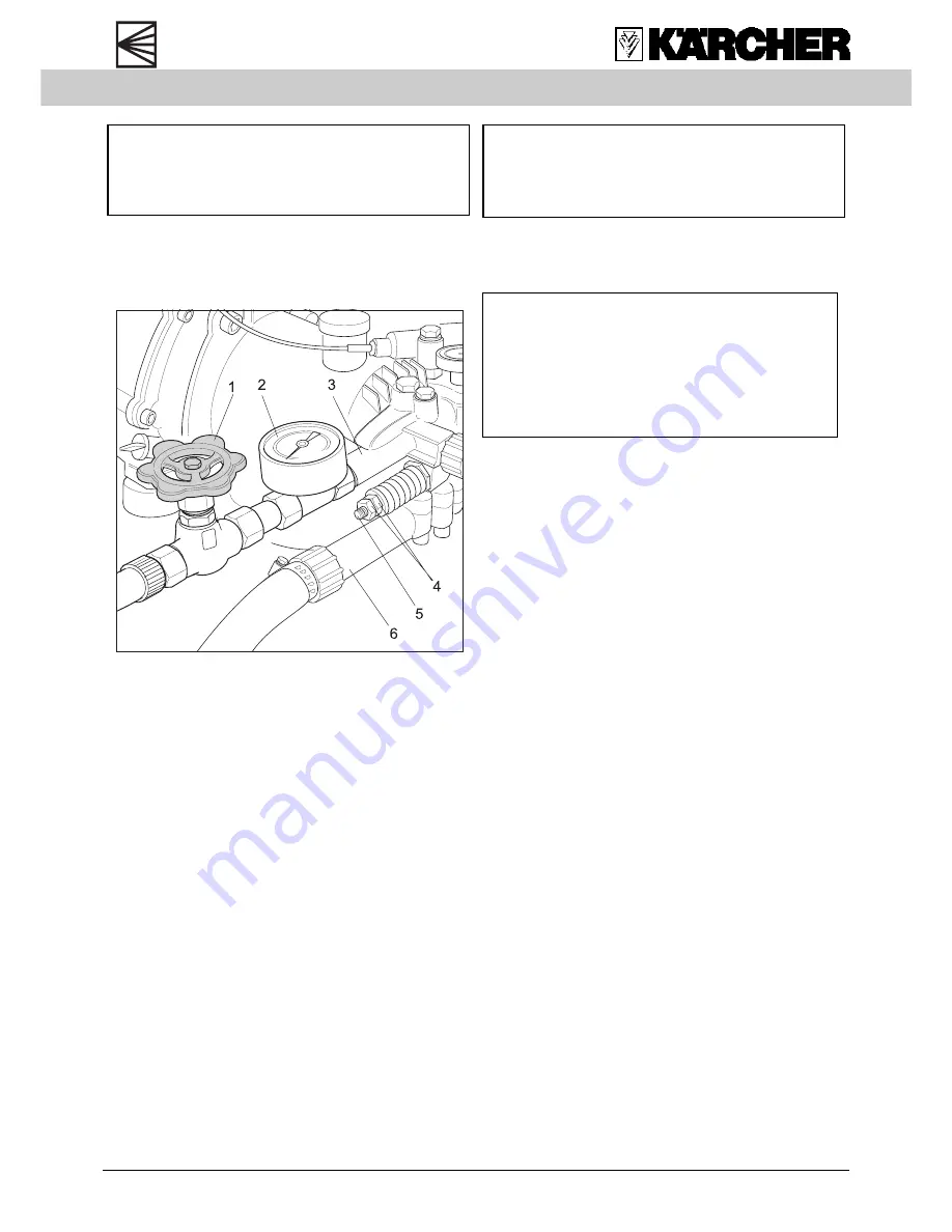
Adjustment overflow valve

Note

Before any adjustments the high-pressure

nozzle, air filter and spark plug must be

checked for damage or wear. All defective

parts must be replaced.

1. Mount test pressure gauge (2), shut-off valve

(1), high-pressure hose and servopress

handgun on high-pressure outlet (3).
The unit pressure gauge is not to be used to

check the operation pressure because it

measures too inaccurate !

2. Set servopress handgun to maximum water

volume and operate the unit.

3. Close shut-off cock (1) slowly until flow rate

has achieved  6,7 to 7,5 litres/min. (see

technical data).  This corresponds to the

smallest servopress setting (flow rate

measured by litres).

4. Now set adjusting screw (4) to operation

pressure 208 to 212 bar (see technical

data) and check with test pressure

gauge.
Increase spring tension: pressure

increases.

Decrease spring tension: pressure

decreases.

5. Open  shut-off valve completely. Close and

open servopress handgun several times.

6. Repeat step 3 and 4 and adjust once more

if required.

7. Finally secure the adjusting screw with

locking nut (4) and seal with safety paint.

1

Shut-off valve

2

Test pressure gauge

3

High-pressure outlet

4

Adjusting screw with locking nut

5

Overflow valve spindle

6

Water inlet connection

Summary of Contents for HD 1050 B Cage

Page 1: ...Page 1 10 InternationalServiceInformation International Service Information June 24th 1999 HD 1050 B New Unit Information HD 1050 B 1 810 987 5 905 950...

Page 2: ...connection 2 Pressureandflowcontrol 3 Servopresshandgun 4 Spraylance 5 Three waynozzle 6 Cleaningagentmeteringvalve 7 Cleaning agent suction hose 8 High pressurepump 9 Engine 10 High pressureconnectio...

Page 3: ...B New Unit Information Technical features pump 1 Pressure gauge 2 Non returnvalve 3 Pressurevalve 4 Oilreservoir 5 Shaftseal 6 Swash plate bearing 7 Swash plate 8 Axial roller bearing 9 Oil drain plu...

Page 4: ...ngagentconnection 4 Controlpressureinjector 5 Pressure gauge 6 Screwplugfornon returnvalve 7 Pressurechamber 8 Connection bore from pressure chamber to ball 9 9 Ball 10 Spring 11 Suctionchamber 12 Con...

Page 5: ...tip of the spindle pushes the ball 9 off its seat so that part of the water can flow through the connection bores 8 and 12 to the suction chamber 11 3 Servopress handgun is completely closed When the...

Page 6: ...elever 2 Inner bowden cable clamping screw 3 Outer bowden cable clamp 4 Throttleleverstopscrew 5 Bowden cable 6 Adjustingscrewwithlockingnut 7 r p m regulator 1 Switch off engine and release pressure...

Page 7: ...nd operate the unit 3 Close shut off cock 1 slowly until flow rate has achieved 6 7 to 7 5 litres min see technical data This corresponds to the smallest servopress setting flow rate measured by litre...

Page 8: ...to 200 bar With this operating pressure the corresponding operating r p m must also be achieved see technical data 3 Close and open servopress handgun several times and check adjustment 4 Open servopr...

Page 9: ...pressure and flow rate Check high pressure nozzle replace if required Check water inlet filter clean if required Check engine speed adjust if required Check spring at overflow valve adjust if require...

Page 10: ...1 mechanicalversion The technical data sheet is on the next edition of the spare parts CD ROM DISIS and in the Intranet KMN folder Central Service Info Int l Technical Data Further operating handbooks...

Reviews: