background image

77

• Данный лазерный уровень автоматически определяет   

  горизонтальную и вертикальную плоскости.

• Лазер излучает одну горизонтальную и две вертикальные

  зеленые круговые линии (все по 360°), которые перекрещиваются   

  под прямым углом на четырех стенах, полу и потолке.

• Самовыравнивание в автоматическом режиме в диапазоне ± 4°.

• Световое и звуковое предупреждение о выходе из диапазона

  выравнивания.

• Импульсы, излучаемые в импульсном режиме, определяются  

  датчиком.

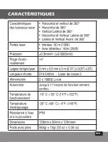
• Макс. рабочий диапазон в помещении — 30 м (100 футов)

• Макс. диапазон обнаружения лазера в импульсном режиме  

  — 60 м (200 футов).

• В ручном режиме возможна угловая разметка.

• Блокирующий механизм защищает лазер во время    

  транспортировки.

• Резьба под штатив 1/4"

• Литой корпус защищен от ударов резиновым покрытием.

• 2 аккумулятора 18650.

• В комплект входят: литий-полимерный аккумулятор, 

  провод micro USB, многофункциональное крепление, 

  сумка для переноски.

ТЕХНИКА БЕЗОПАСНОСТИ

ПРЕДУПРЕЖДЕНИЕ

Этот прибор является источником излучения, которое 

относится к Классу II в соответствии со стандартом EN 

60825 -1

Лазерное излучение может привести к 

серьезным повреждениям глаз

• Не допускайте попадания лазерного луча в глаза

• Не устанавливайте лазерный уровень так, чтобы 

  он мог непреднамеренно ослеплять вас или других    

  людей.

• Не используйте лазерный уровень вблизи детей и 

  не позволяйте детям использовать лазерный уровень.

• Не допускайте попадания лазерного луча в глаза 

через увеличительные оптические устройства, такие 

как бинокль или телескоп, так как это повышает 

степень повреждения глаз.


ПРЕДУПРЕЖДЕНИЕ:


Этот прибор содержит           

свинец в припое, также некоторые электрические   

части содержат химические вещества, которые 

известны в штате Калифорния как вызывающие рак, 

дефекты у новорождённых или другие нарушения 

репродуктивной функции. 

(Кодекс Здоровья и Безопасности штата Калифорния, 

Раздел 25249.6  положение 65)

Summary of Contents for CROSSLIGHT 3D LASER GREEN 863G

Page 1: ...CROSSLIGHT 3D LASER GREEN Model No 863G User Manual Manual del usuario Manuel d utilisation 2 x 18650 RECHARGEABLE Up to 60m 200...

Page 2: ...Laser is a laser level with 3 green diodes that emit 3 circular lines The laser is innovatively designed for a very broad range of professional and DIY jobs including Hanging cabinets and shelves Set...

Page 3: ...3 CONTENTS Features 4 Safety instructions 5 6 Battery installation Safety 7 8 Overview 9 Operating instructions 10 11 Maintenance 12 Field calibration test 13 22 Specifications 23 Warranty 24 25...

Page 4: ...laser is positioned within its self leveling range which is 4 Visual and audible warning when the laser level is out of leveling range Pulse mode emits pulses that can be detected by a detector Max in...

Page 5: ...te the laser level near children or let children operate the laser level Do not look into a laser beam using magnifying optical devices such as binoculars or a telescope since it will increase the lev...

Page 6: ...s eye injury Do not drop the unit Do not use solvents to clean the laser unit Do not use in temperatures below 10 C or above 50 C 14 F to 122 F Do not operate the laser in explosive atmospheres such a...

Page 7: ...light 3D Laser uses 2 rechargeable 18650 Lithium batteries Installation 1 Press down the latch of the battery cover 2 Insert the two 18650 batteries according to the polarity marks on the lid of the b...

Page 8: ...RNING Batteries can deteriorate leak or explode and can cause injury or fire 1 Do not shorten the battery terminals 2 Do not dispose of battery into household waste 3 Do not dispose of battery in fire...

Page 9: ...On Off Locking Switch 2 Keypad a Beam Selector Button b Manual Mode Button c Pulse Mode Button d Battery LED indicator 3 Horizontal Laser Beam 4 Front Vertical Laser Beam 5 Side Vertical Laser Beam 6...

Page 10: ...edly to see the laser beams output pattern in the following sequence First press Horizontal beam only Second press Horizontal and side vertical beams Third press Side vertical beam only Fourth press F...

Page 11: ...ctor button a 4 Tilt the laser to the desired angle and mark the slope 5 Slide the ON OFF Switch 1 to ON mode to activate the automatic mode NOTE If the initial inclination of the laser level is above...

Page 12: ...he laser level with a clean soft cloth Do not use solvents Although the laser level is dust and dirt resistant to a certain degree don t store in dusty places Long term exposure may damage internal mo...

Page 13: ...heck the perpendicularity between the 2 vertical beams 1 Checking the height accuracy of the cross created by the front vertical Horizontal lines Up and down deviation 1 Set up the laser on a table or...

Page 14: ...laser and verify that the 2 vertical lines pass through a1 and c1 7 Mark on wall B the the intersection point of the beams as b1 see figure 2 B A C a1 c1 x x 0 5 m 2 m B A C a1 b1 c1 x x x 0 5 m 2 m...

Page 15: ...roject all 3 lasers beams 10 Verify that the vertical line passes through a1 and b1 11 On wall B mark the intersection point of the beams as b2 see figure 3 12 Rotate the laser 180 Reposition the lase...

Page 16: ...Measure the distances a a2 a1 b b1 b2 15 The difference a b should be no more than 3 mm otherwise send the laser level to a qualified technician for repair B A C a2 a1 b2 b1 x x x x 0 5 m 2 m 180 Fig...

Page 17: ...ly 0 5 meters from wall A and 2 meters from wall C 3 Turn on the laser in Automatic mode to project all 3 lasers beams 4 Direct the cross lines of the horizontal beam and the front vertical beam towar...

Page 18: ...Turn on the device and select the front vertical beam alone Project it on the plumb line 5 Position the laser so the vertical beam will intersect with the plumb line below the hanging point 6 Mark poi...

Page 19: ...e no more than 1mm otherwise send the laser level to a qualified technician for repair 4 Checking the Accuracy of the side vertical beam For the second vertical beam repeat the previous marking proced...

Page 20: ...s beam selector button to project the front and the side vertical beams 3 Mark the center of the front vertical beam in 3 places Point a1 on the left wall A in the middle of the vertical line Point b1...

Page 21: ...ass through c1 on the table and the side laser beam passes through the marks a1 and b1 on the walls A and B respectively 6 Mark as c3 the center of the side vertical beam on wall C at the same height...

Page 22: ...22 7 The distance between c2 and c3 should be no more than 1 5mm otherwise send the laser level to a qualified technician for repair c3 c2 X c1 XX X a1 2 5m 2 5m A b1 X B C 5 m Figure 8...

Page 23: ...With detector 60m 200ft Accuracy 0 3mm m 0 0003in in Self leveling Range 4 Laser line width 2 mm 0 5mm 5m 0 10 0 02 at 20 Wavelength 510 540 Laser Class II Power supply 2 x 18650 Li Ion Battery life U...

Page 24: ...point of sale alongside your proof of purchase 2 After a return authorization procedure is initiated the laser level will be sent to an authorized repair lab 3 Once completed the product will be retur...

Page 25: ...ished by the European Directive 2014 30 EU and the Low Voltage Directive LVD 2014 35 EU EC DECLARATION OF CONFORMITY We declare under our responsibility that the product 863G is in accordance with the...

Page 26: ...a gama de tareas profesionales y de bricolaje incluyendo Colgar gabinetes y estantes Colocar azulejos en pisos y paredes Instalar paneles de yeso y colocar cielorrasos ac sticos Enmarcar y alinear ven...

Page 27: ...icas 28 Instrucciones de seguridad 29 30 Instalaci n de pilas y seguridad 31 32 Descripci n general 33 Instrucciones de funcionamiento 34 36 Mantenimiento 36 Prueba de calibraci n 37 46 Especificacion...

Page 28: ...Pulso emite pulsos que pueden ser detectados por un detector Rango de trabajo m x en interiores 30m El rango m x detectable del l ser en modo pulso es de 60m El modo manual permite dise o marcaci n an...

Page 29: ...e el nivel l ser cerca de ni os ni permita a los ni os utilizar el nivel l ser No mire a un rayo l ser utilizando equipos pticos de aumento tal como prism ticos o telescopio ya que esto aumentar el ni...

Page 30: ...iores a 50 C 14 F a 122 F No opere el l ser en atm sferas explosivas tales como l quidos inflamables gases o polvo Las chispas pueden causar ignici n Cuando no est en uso quite la bater a active el bl...

Page 31: ...Crosslight 3D usa 2 bater as 18650 recargables Instalaci n 1 Presione el pestillo de la tapa de las bater as 2 Introduzca las dos bater as 18650 seg n las marcas de polaridad en la tapa del compartimi...

Page 32: ...incendios 1 No acorte los terminales de las pilas 2 No recargue las pilas alcalinas 3 No mezcle pilas viejas y nuevas 4 No deseche las pilas en la basura hogare a 5 No deseche las pilas en el fuego Ca...

Page 33: ...ado 2 Teclado a Bot n selector de rayos b Bot n de modo manual c Bot n de modo de pulsos d Indicador LED de bater as 3 Rayo l ser horizontal 4 Rayo l ser frontal vertical 5 Rayo l ser lateral vertical...

Page 34: ...ver el patr n de salida de los rayos l ser en la secuencia siguiente Primera presi n Solo rayo horizontal Rayo horizontal y laterales verticales Tercera presi n Solo rayo vertical lateral Cuarta presi...

Page 35: ...da 3 segundos 3 Elija los rayos necesarios presionando el bot n selector de rayos a 4 Incline el l ser al ngulo deseado y marque la pendiente 5 Ponga el interruptor ON OFF 1 en modo ON para activar el...

Page 36: ...ser con un pa o suave y limpio No utilice disolventes Aunque el nivel l ser es resistente al polvo y la suciedad en cierta medida no lo almacene en lugares polvorientos ya que una exposici n de largo...

Page 37: ...dicularidad entre los 2 rayos verticales 1 Comprobaci n de la precisi n de la altura de la intersecci n de las l neas laterales n 5 y horizontal Desviaci n hacia arriba y hacia abajo 1 Coloque el l se...

Page 38: ...r el l ser y verifique que las 2 l neas verticales pasan por a1 y c1 7 Marque en la pared B el centro del punto de intersecci n como b1 v ase la figura n 2 B A C a1 c1 x x 0 5 m 2 m B A C a1 b1 c1 x x...

Page 39: ...yectar los 3 rayos l ser 10 Verifique que la l nea vertical pase por a1 y b1 11 Marque en la pared B el centro del punto de intersecci n como b2 v ase la figura n 3 12 Gire el l ser 180 Reposicione el...

Page 40: ...ida las distancias a a2 a1 b b1 b2 15 La diferencia a b no debe ser superior a 3 mm De lo contrario el nivel l ser debe ser reparado por un t cnico calificado B A C a2 a1 b2 b1 x x x x 0 5 m 2 m 180 F...

Page 41: ...pared C 3 Desbloquee el p ndulo y presione el bot n a dos veces para proyectar los 3 rayos l ser 4 Dirija las l neas transversales del rayo horizontal y del rayo vertical frontal n 4 hacia la pared A...

Page 42: ...ulo y pulse el bot n para proyectar el rayo vertical frontal n 4 hacia la l nea de plomada 5 Gire el l ser de modo que el rayo vertical se fusione con la l nea de plomada por debajo del punto de suspe...

Page 43: ...lo contrario el nivel l ser debe ser reparado por un t cnico calificado 4 Comprobaci n de la precisi n rayo vertical lateral n 5 Para el segundo rayo vertical repita el procedimiento de marcaci n indi...

Page 44: ...os veces el bot n a para proyectar el rayo vertical frontal y el rayo vertical lateral 3 Marque el centro del rayo vertical lateral en 3 lugares Punto a1 sobre la pared izquierda A en el centro de la...

Page 45: ...asen a trav s de c1 sobre la mesa y el rayo frontal pase a trav s de las marcas a1 y b1 sobre las paredes A y B respectivamente 6 Marque como c3 el centro del rayo vertical lateral sobre la pared C a...

Page 46: ...46 7 La distancia entre c2 y c3 no debe ser superior a 1 5 mm De lo contrario el nivel l ser debe ser reparado por un t cnico calificado c3 c2 X c1 XX X a1 2 5m 2 5m A b1 X B C 5 m Figura 8...

Page 47: ...nivelaci n 4 Ancho de l nea l ser 2 mm 0 5mm 5m 0 10 0 02 a 20 Longitud de onda 510 540nm L ser de clase II Alimentaci n de tensi n 2 x 18650 Li Ion Duraci n de la bater a Hasta 11 horas de funcionami...

Page 48: ...al punto de venta junto con su comprobante de compra 2 Despu s de iniciar un procedimiento de autorizaci n de retorno el nivel l ser ser enviado a un laboratorio de reparaci n autorizado 3 Una vez com...

Page 49: ...tablecido por la Directiva Europea 2014 30 EU y el Reglamento para baja tensi n 2014 35 EU DECLARACI N DE CONFORMIDAD CE Declaramos bajo nuestra responsabilidad que el producto 863G est en acuerdo con...

Page 50: ...d utilisations dans un cadre professionnel ou de bricolage notamment L installation d armoires et d tag res La pose de carrelages L installation de cloisons s ches et de plafonds acoustiques L encadre...

Page 51: ...51 CONTENU Fonctions 52 Consignes de s curit 53 54 Installation des piles et s curit 55 56 Vue d ensemble 57 Utilisation 58 59 Entretien 60 Test d talonnage 61 70 Caract ristiques 71 Garantie 72 73...

Page 52: ...qui peuvent tre d tect es par un d tecteur Une port e maximale de fonctionnement int rieur de 30 m 100 Laport emaximaled tectabledulaserenmodepuls estde60m 200 Le mode manuel permet une disposition e...

Page 53: ...proximit d enfants ou laisser des enfants utiliser le niveau laser Ne pas regarder dans le faisceau laser avec un mat riel optique grossissant des jumelles ou un t lescope par exemple pouvant aggraver...

Page 54: ...res 50 C 14 F 122 F N utilisez pas le laser dans un environnement explosif des liquides gaz ou poussi res inflammables Des tincelles peuvent d clencher un incendie Lorsqu il n est pas utilis retirez l...

Page 55: ...ght utilise 2 piles rechargeables de 18650 Installation 1 Appuyez sur le loquet du couvercle des piles 2 Ins rez les deux piles 18650 en respectant les marques de polarit sur le couvercle du compartim...

Page 56: ...es des piles 2 Ne jetez pas les piles dans les ordures m nag res 3 Ne jetez pas les piles dans un feu 4 Les piles d fectueuses ou d charg es doivent tre jet es confor m ment la r glementation locale 5...

Page 57: ...a Bouton de s lection de faisceau b Bouton de mode manuel c Bouton de mode puls d Voyant LED de batterie 3 Faisceau laser horizontal 4 Faisceau laser vertical avant 5 Faisceau laser vertical lat ral...

Page 58: ...sceaux laser dans la s quence suivante Premi re appui Faisceau horizontal uniquement Deuxi me appui Faisceaux horizontaux et verticaux lat raux Troisi me appui Faisceau vertical lat ral uniquement Qua...

Page 59: ...hoisissez les faisceaux n cessaires en appuyant sur le bouton de s lection des faisceaux a 4 Inclinez le laser l angle souhait et marquez la pente 5 Positionnez l interrupteur ON OFF MARCHE ARR T 1 su...

Page 60: ...ropre N utilisez pas de solvants Bien que le niveau laser r siste dans une certaine mesure la poussi re et la salet ne le stockez pas dans des endroits poussi reux car une exposition prolong e peut en...

Page 61: ...ularit entre les deux faisceaux verticaux 1 V rification de la pr cision verticale de la croix cr e par les lignes lat rale n 5 et horizontale cart haut bas 1 Placez le laser sur une table ou au sol e...

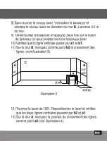
Page 62: ...v rifiez que les deux lignes verticales passent par les points a1 et c1 7 Marquez comme point b1 le croisement des lignes sur le mur B voir illustration 2 B A C a1 c1 x x 0 5 m 2 m B A C a1 b1 c1 x x...

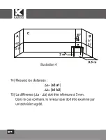
Page 63: ...les trois faisceaux laser 10 V rifiez que la ligne verticale passe par a1 et b1 11 Sur le mur B marquez comme point b2 le croisement des lignes voir illustration 3 12 Tournez le laser de 180 Repositi...

Page 64: ...rez les distances a a2 a1 b b1 b2 15 La diff rence a b doit tre inf rieure 3 mm Dans le cas contraire le niveau laser doit tre examin par un technicien agr B A C a2 a1 b2 b1 x x x x 0 5 m 2 m 180 illu...

Page 65: ...ur C 3 D verrouillez le balancier et appuyez deux fois sur le bouton de faisceau a projeter les trois faisceaux laser 4 Projetez les lignes crois es du faisceau horizontal et du faisceau vertical fron...

Page 66: ...le bouton pour projeter le faisceau vertical frontal n 4 en direction du fil plomb 5 Tournez le laser afin que le faisceau vertical se superpose avec la ligne d aplomb sous le point de suspension 6 S...

Page 67: ...le cas contraire le niveau laser doit tre examin par un technicien agr 4 V rification de la pr cision du faisceau vertical lat ral n 5 Pour le second faisceau vertical r p tez les op rations de marqua...

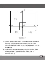
Page 68: ...er et appuyez deux fois sur le bouton de faisceau a projeter les faisceaux verticaux frontal et lat ral 3 Marquez le centre du faisceau vertical lat ral en 3 endroits point a1 sur le mur A gauche au m...

Page 69: ...nt par c1 sur la table et que le faisceau laser avant passe par les marques a1 et b1 sur les murs A et B 6 Sur le mur C marquez le centre du faisceau vertical lat ral comme point c3 la m me hauteur qu...

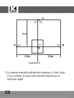
Page 70: ...70 7 La distance entre c2 et c3 doit tre inf rieure 1 5mm Dans le cas contraire le niveau laser doit tre examin par un technicien agr c3 c2 X c1 XX X a1 2 5m 2 5m A b1 X B C 5 m illustration 8...

Page 71: ...0 3mm m 0 0003in in Plage d auto nivellement 4 Largeurdelignelaser 2 mm 0 5 mm 5 m 0 10 0 02 20 Longueur d onde 510 540nm Laser de classe 2 Alimentation 2 x 18650 Li Ion Autonomie Jusqu 11 heures de...

Page 72: ...uillez le retourner au point de vente accompagn de votre preuve d achat 2 Une fois la proc dure d autorisation de retour initi e le niveau laser sera envoy un laboratoire de r paration agr 3 Une fois...

Page 73: ...que CEM tabli par la directive europ enne 2014 30 EU et le r glement pour basse tension 2014 35 EU D CLARATION DE CONFORMIT CE Nous d clarons sous notre responsabilit que le produit 863G est conforme...

Page 74: ...74 Kapro 863G Crosslight 3D 863G Crosslight 360 RU 2 x 18650 Up to 60m 200...

Page 75: ...75 76 77 78 79 80 81 82 83 84 85 94 95 96 97...

Page 76: ...76 360 4 30 100 60 200 1 4 2 18650 micro USB...

Page 77: ...77 II EN 60825 1 25249 6 65...

Page 78: ...78 10 C 50 C...

Page 79: ...79 863G Crosslight 3D 18650 1 2 18650 3...

Page 80: ...80 1 2 3 4 5 d 18650...

Page 81: ...81 1 2 a b c d 3 4 5 6 7 1 4 1 2 3 4 5 7 6 a b d c...

Page 82: ...82 4 1 360 2 360 1 2 1 ON 3 3 4 4 5 1 OFF...

Page 83: ...83 863G Crosslight 3D Laser 1 2 b 2 3 3 4 5 ON OFF 1 ON 4...

Page 84: ...84...

Page 85: ...85 Kapro 1 2 3 4 5 1 1 A B C 5 2 0 5...

Page 86: ...86 B A C a1 c1 x x 0 5 m 2 m 3 a 4 5 1 c1 1 5 0 5 1 2...

Page 87: ...87 6 180 B 2 a1 c1 7 b1 2 8 B 0 5 B 9 a 10 a1 b1 11 b2 3 B A C a1 b1 c1 x x x 0 5 m 2 m 180 0 5 2 2...

Page 88: ...88 12 180 b2 a1 13 a2 4 B A C a1 b2 b1 x x x 0 5 m 2 m 0 5 3 2 B A C a2 a1 b2 b1 x x x x 0 5 m 2 m 180 0 5 4 2 14 a a2 a1 b b1 b2 15 a b 3...

Page 89: ...89 2 1 A B C 5 2 0 5 3 a 4 5 5 15 3 1 3 2 a1 5...

Page 90: ...90 a1 x 3 2 4 4 5 6 2 a1 6 5 3...

Page 91: ...91 2 m a1 a2 x x x 7 a1 a2 1 4 5 1 7 6 2...

Page 92: ...92 5 5 5 3 1 2 a 3 3 1 b1 c1 2 4 c2 7...

Page 93: ...93 c2 X c1 X X a1 2 5m 2 5m A b1 X B C 5 m 7 2 5 2 5 5 5 90 c1 a1 b1 6 c3 8...

Page 94: ...94 c3 c2 X c1 XX X a1 2 5m 2 5m A b1 X B C 5 m 8 2 5 2 5 5 7 2 3 1 5...

Page 95: ...95 360 360 360 360 360 30 60 0 3 0 0003in in 4 2 0 5 5 510 540 II 2 18650 11 10 C 50 C 20 C 60 C IP54 12 8 x 8 x 12 560 10...

Page 96: ...96 Kapro 1 2 3...

Page 97: ...97 CEM 2014 30 EU 2014 35 EU 863G 2014 30 EU 2011 65 EU EN60825 1 2014 EN61326 1 2013...

Page 98: ...98...

Page 99: ...99...

Page 100: ...1 00 Rev 4 0 2023 Kapro Industries Ltd...

Reviews: