background image

91

a1

Figure # 5

 # הנומת

5

X

approximately 3m

3) Установите лазерный уровень на штатив или другую  

    устойчивую поверхность на расстоянии около 2 метров  

    перед стеной.

4) Разблокируйте маятник и выберите проекцию  


    переднего вертикального лазера (# 4) по направлению  

    к линии отвеса.

5) Поверните прибор так, чтобы вертикальная лазерная  

    линия совпадала с линией отвеса  вверху, под точкой  

    крепления.

6) Отметьте на стене точку 

а2

 по лазерной линии на той  

    же высоте, что и 

a1

. (См. рис. №6). 

рисунок № 5

приблизительно 3 м

Summary of Contents for 883G

Page 1: ...Prolaser 3D All Lines GREEN Model No 883G Li ion 165 50m RECHARGEABLE Up to 70m 230 4 AA INCLUDED User Manual Manual del usuario Manuel d utilisation...

Page 2: ...atively designed for a very broad range of professional and DIY jobs including Hanging cabinets and shelves Setting floor and wall tiles Drywall installation and hanging acoustic ceilings Framing and...

Page 3: ...3 CONTENTS Features 4 Safety instructions 5 6 Battery installation Safety 7 8 Overview 9 Operating instructions 10 12 Maintenance 13 Field calibration test 14 23 Specifications 24 Warranty 25...

Page 4: ...y a detector Max indoor working range 30 m 100 with green goggles The max detectable range of the laser in pulse mode is 70m 230 Manual mode allows angular layout marking IP65 Rated for water and dust...

Page 5: ...evel Do not look into a laser beam using magnifying optical devices such as binoculars or a telescope since it will increase the level of eye injury WARNING This product contains lead in soldered join...

Page 6: ...0 C or above 50 C 14 F to 122 F Do not operate the laser in explosive atmospheres such as flammable liquids gases or dust Sparks can cause ignition When not in use remove the battery engage the pendul...

Page 7: ...included Installation 1 Press down the latch of the battery cover 2 Insert the Li Ion battery pack or the battery compartment with the 4 AA Alkaline batteries with the terminal contacts forward accord...

Page 8: ...the charging the LED indicator on the charging adaptor will be red and then green once fully charged 1 Charger 2 Charging adaptor 3 LED indicator 4 Rechargeable battery WARNING Battery can deteriorat...

Page 9: ...ypad a Beam Selector Manual mode button b Beam Battery indicator c Pulse Mode button d Pulse Mode indicator 3 Horizontal laser beam window 4 Forward vertical laser beam window 5 Side vertical laser be...

Page 10: ...al side beam instead of the horizontal beam 4 An additional click on the beam selector button will turn on a 360 vertical front beam in addition to the side vertical beam 5 One more click on the beam...

Page 11: ...red angle 4 To choose another beam briefly press the beam selector button a it will turn on a 360 vertical side beam instead of the horizontal beam 5 An additional click on the beam selector button a...

Page 12: ...he laser beams 1 The pulse mode can be activated both in Automatic and in Manual mode 2 Turn on the laser level to the required mode 3 Press the Pulse mode button c to activate it The Pulse mode indic...

Page 13: ...e laser level with a clean soft cloth Do not use solvents Although the laser level is dust and dirt resistant to a certain degree don t store in dusty places as long term exposure may damage internal...

Page 14: ...ck the perpendicularity between the 2 vertical beams 1 Checking the Height Accuracy of the cross created by the lateral 5 Horizontal lines Up and down deviation 1 Set up the laser on a table or on the...

Page 15: ...Reposition the laser and verify that the 2 vertical lines pass through a1 and c1 7 Mark on wall B the center of the cross beams as b1 see figure 2 A B Figure 1 C a1 0 5m c1 X 2m X approximately 5m A B...

Page 16: ...Beam Selector a twice to project all 3 lasers beams 10 Verify that the vertical line passes through a1and b1 11 On wall B mark the center of the cross beams as b2 see figure 3 12 Turn the laser 180 Re...

Page 17: ...4 Measure the distances a a2 a1 b b1 b2 15 The difference a b should be no more than 3 mm otherwise send the laser level to a qualified technician for repair A B Figure 4 C a2 0 5m X 2m b1 X b2 X a1 X...

Page 18: ...om wall A and 2 meters from wall C 3 Unlock the pendulum and press the Beam Selector a twice to project all 3 lasers beams 4 Direct the cross lines of the horizontal beam and the forward vertical beam...

Page 19: ...k the pendulum and press the button to project the vertical forward beam 4 towards the plumb line 5 Turn the laser so the vertical beam will merge with the plumb line below the hanging point 6 Mark po...

Page 20: ...more than 1mm otherwise send the laser level to a qualified technician for repair 4 Checking the Accuracy of the side Vertical beam 5 For the second vertical beam repeat the previous marking procedur...

Page 21: ...he button Beam Selector a twice to project the forward and the side vertical beams 3 Mark the center of the side vertical beam in 3 places Point a1 on the left wall A in the middle of the vertical lin...

Page 22: ...through c1 on the table and the forward laser beam passes through the marks a1 and b1 on the walls A and B respectively 6 Mark as c3 the center of the side vertical beam on wall C at the same height a...

Page 23: ...23 7 The distance between c2 and c3 should be no more than 1 5mm otherwise send the laser level to a qualified technician for repair c3 X c1 X X a1 2 5m 2 5m A b1 X B C Figure 8 5m X c2...

Page 24: ...ing Range 2 5 Laser line width 2 mm 0 5mm 5m 0 10 0 02 at 20 Wavelength 515 525nm Laser Class II Power supply 2600mAh Li Ion battery 7 4V or 4 AA Alkaline batteries Battery life Up to 8 hours of conti...

Page 25: ...chase with proof of purchase Model 883G The serial number sticker is positioned inside the battery compartment CE CONFORMITY CERTIFICATE This product meets the standards of the Electromagnetic Compati...

Page 26: ...e para una amplia gama de trabajos profesionales y de bricolaje como Colgar armarios y estantes Colocar suelos y revestimientos Instalar placas de yeso y techos ac sticos Enmarcar y alinear puertas y...

Page 27: ...ticas 28 Instrucciones de seguridad 29 30 Instalaci n de pilas y seguridad 31 32 Descripci n general 33 Instrucciones de funcionamiento 34 36 Mantenimiento 37 Prueba de calibraci n 38 47 Especificacio...

Page 28: ...Max rango de trabajo en interiores es de 30 m 100 con gafas Beamfinder El alcance m ximo de detecci n del l ser en modo Pulso es de 70m 230 El modo manual permite la disposici n el marcado angular Cla...

Page 29: ...vel l ser No mire a un rayo l ser utilizando equipos pticos de aumento tal como prism ticos o telescopio ya que esto aumentar el nivel de lesi n ocular ADVERTENCIA Este producto contiene plomo en las...

Page 30: ...0 C 14 F 122 F No opere el l ser en atm sferas explosivas tales como l quidos inflamables gases o polvo Las chispas de la herramienta pueden causar ignici n Cuando no est en uso apague la unidad engan...

Page 31: ...o de pilas est incluido Instalaci n 1 Presione hacia abajo el pestillo de la tapa del compartimiento de pilas 2 Inserte la pila de iones de litio o el compartimiento de pilas con las 4 pilas alcalinas...

Page 32: ...acuerdo con las normativas locales 7 Mantenga las pilas fuera del alcance de los ni os Cargue la pila de litio o use pilas alcalinas AA nuevas si el indicador de haz pila b comienza a parpadear en lu...

Page 33: ...ctor de rayo bot n de modo Manual b Indicador de rayo pila c Bot n de modo Pulso d Indicador de modo Pulso 3 Ventana de rayo l ser horizontal 4 Ventana de rayo l ser vertical hacia adelante 5 Ventana...

Page 34: ...ayohorizontalyseproyectar unrayoverticallateralde360 4 Haga un clic adicional en el bot n de selecci n de l neas a y se proyectar hacia adelante un rayo vertical de 360 adem s del rayo vertical latera...

Page 35: ...ncline el l ser al ngulo deseado 4 Para elegir otro rayo pulse brevemente el bot n de selecci n de l neas a y se prendera un rayo l ser vertical lateral en vez del horizontal 5 Pulse brevemente el bot...

Page 36: ...tector detecte los rayos l ser 1 El modo pulso se puede activar en modo Automatico y en modo Manual 2 Ponga el interruptor n 1 en la posici n ON encendido 3 Presione el bot n c para activar el modo Pu...

Page 37: ...ser con un pa o suave y limpio No utilice disolventes Aunque el nivel l ser es resistente al polvo y a la suciedad en cierta medida no lo almacene en lugares polvorientos ya que una exposici n prolong...

Page 38: ...icularidad entre los 2 rayos verticales 1 Comprobaci n de la precisi n de la altura de la intersecci n de las l neas laterales n 5 y horizontal Desviaci n hacia arriba y hacia abajo 1 Coloque el l ser...

Page 39: ...rifique que las 2 l neas verticales pasan por a1 y c1 7 Marque en la pared B el centro del punto de intersecci n como b1 v ase la figura n 2 A B Figure 1 C a1 0 5m c1 X 2m X approximately 5m A B Figur...

Page 40: ...ar los 3 rayos l ser 10 Verifique que la l nea vertical pase por a1 y b1 11 Marque en la pared B el centro del punto de intersecci n como b2 v ase la figura n 3 12 Gire el l ser 180 Reposicione el l s...

Page 41: ...las distancias a a2 a1 b b1 b2 15 La diferencia a b no debe ser superior a 3 mm De lo contrario el nivel l ser debe ser reparado por un t cnico calificado A B Figure 4 C a2 0 5m X 2m b1 X b2 X a1 X 18...

Page 42: ...pared C 3 Desbloquee el p ndulo y presione el bot n a dos veces para proyectar los 3 rayos l ser 4 Dirija las l neas transversales del rayo horizontal y del rayo vertical frontal n 4 hacia la pared A...

Page 43: ...l bot n para proyectar el rayo vertical frontal n 4 hacia la l nea de plomada 5 Gire el l ser de modo que el rayo vertical se fusione con la l nea de plomada por debajo del punto de suspensi n 6 Marqu...

Page 44: ...ntrario el nivel l ser debe ser reparado por un t cnico calificado 4 Comprobaci n de la precisi n rayo vertical lateral n 5 Para el segundo rayo vertical repita el procedimiento de marcaci n indicado...

Page 45: ...os veces el bot n a para proyectar el rayo vertical frontal y el rayo vertical lateral 3 Marque el centro del rayo vertical lateral en 3 lugares Punto a1 sobre la pared izquierda A en el centro de la...

Page 46: ...a trav s de c1 sobre la mesa y el rayo frontal pase a trav s de las marcas a1 y b1 sobre las paredes A y B respectivamente 6 Marque como c3 el centro del rayo vertical lateral sobre la pared C a la m...

Page 47: ...47 7 La distancia entre c2 y c3 no debe ser superior a 1 5 mm De lo contrario el nivel l ser debe ser reparado por un t cnico calificado c3 X c1 X X a1 2 5m 2 5m A b1 X B C Figure 8 5m X c2 Figura 8...

Page 48: ...l nea l ser 2 mm 0 5mm 5m 0 10 0 02 a 20 Longitud de onda 515 525nm L ser de clase II Alimentaci n de tensi n 2600mAh Li Ion pila 7 4V o 4 pilas alcalinas AA incluidas Duraci n de la bater a Hasta 8...

Page 49: ...do el comprobante de compra Modelo 883G La etiqueta con el n mero de serie est colocada en el interior del compartimiento de pilas CERTIFICADO DE CONFORMIDAD CE Este producto cumple con las normas de...

Page 50: ...er se destine de tr s nombreuses t ches professionnelles ou de bricolage notamment Pose d tag res et de placards Pose de carrelage sol et mur Installationdecloisonss chesetposedeplafondsacoustiques En...

Page 51: ...51 CONTENU Fonctions 52 Consignes de s curit 53 54 Installation des piles et s curit 55 56 Vue d ensemble 57 Utilisation 58 60 Entretien 61 Test d talonnage 62 71 Caract ristiques 72 Garantie 73...

Page 52: ...er La port e maximale d tectable du laser en mode Pulse est de 70m 230 Mode manuel pour le tra age et le marquage d angles Indice de protection IP65 contre la pluie et la poussi re Syst me de verrouil...

Page 53: ...pas regarder dans le faisceau laser avec un mat riel optique grossissant des jumelles ou un t lescope par exemple pouvant aggraver les l sions oculaires ATTENTION Ce produit contient des soudures au p...

Page 54: ...14 F 122 F Ne pas utiliser en environnement inflammable tel qu en pr sence de liquides gaz ou poussi res infammables Les tincelles peuvent causer allumage Lorsqu il n est pas utilis teindre l apparei...

Page 55: ...calines AA compartiment piles inclus Installation 1 Appuyez sur le loquet du couvercle de la pile 2 Ins rez le bloc batterie Lithium ou le compartiment pile avec les 4 piles alcalines AA avec les cont...

Page 56: ...ses au rebut conform ment la r glementation en vigueur 7 Tenir les piles hors de port e des enfants Rechargez la pile Lithium ou utilisez des piles alcalines AA neuves si l indicateur de faisceau pile...

Page 57: ...sceau bouton de mode Manuel b Faisceau indicateur de piles c Bouton de mode Pulse d Indicateur de mode Pulse 3 Fen tre de faisceau laser horizontal 4 Fen tre de faisceau laser vertical avant 5 Fen tre...

Page 58: ...er le faisceau horizontal et projeter le faisceau vertical lat ral 360 4 Appuyez de nouveau sur le bouton de faisceau a pour activer le faisceau frontal de 360 avec le faisceau vertical lat ral 5 Une...

Page 59: ...b s allumera 3 Pour marquer une inclinaison inclinez le laser l angle d sir 4 Pour s lectionner un autre faisceau appuyez bri vement sur le bouton a 5 Appuyez bri vement sur le bouton defaisceau a Le...

Page 60: ...r les faisceaux laser 1 Le mode Pulse est disponible en mode automatique 2 Poussez l interrupteur n 1 en position ON 3 Appuzez sur le bouton de faisceau a pendant 3 secondes pour engager le mode Pulse...

Page 61: ...r l aide d un chiffon propre et doux N utilisez pas de solvants Bien que le niveau laser soit r sistant l eau et la poussi re ne le remisez pas en un endroit poussi reux une longue exposition tant sus...

Page 62: ...ularit entre les deux faisceaux verticaux 1 V rification de la pr cision verticale de la croix cr e par les lignes lat rale n 5 et horizontale cart haut bas 1 Placez le laser sur une table ou au sol e...

Page 63: ...s deux lignes verticales passent par les points a1 et c1 7 Marquez comme point b1 le croisement des lignes sur le mur B voir illustration 2 A B Figure 1 C a1 0 5m c1 X 2m X approximately 5m A B Figure...

Page 64: ...trois faisceaux laser 10 V rifiez que la ligne verticale passe par a1 et b1 11 Sur le mur B marquez comme point b2 le croisement des lignes voir illustration 3 12 Tournez le laser de 180 Repositionne...

Page 65: ...les distances a a2 a1 b b1 b2 15 La diff rence a b doit tre inf rieure 3 mm Dans le cas contraire le niveau laser doit tre examin par un technicien agr A B Figure 4 C a2 0 5m X 2m b1 X b2 X a1 X 180 i...

Page 66: ...ur C 3 D verrouillez le balancier et appuyez deux fois sur le bouton de faisceau a projeter les trois faisceaux laser 4 Projetez les lignes crois es du faisceau horizontal et du faisceau vertical fron...

Page 67: ...ur projeter le faisceau vertical frontal n 4 en direction du fil plomb 5 Tournez le laser afin que le faisceau vertical se superpose avec la ligne d aplomb sous le point de suspension 6 Sur le mur mar...

Page 68: ...s contraire le niveau laser doit tre examin par un technicien agr 4 V rification de la pr cision du faisceau vertical lat ral n 5 Pour le second faisceau vertical r p tez les op rations de marquage 1...

Page 69: ...er et appuyez deux fois sur le bouton de faisceau a projeter les faisceaux verticaux frontal et lat ral 3 Marquez le centre du faisceau vertical lat ral en 3 endroits point a1 sur le mur A gauche au m...

Page 70: ...ar c1 sur la table et que le faisceau laser avant passe par les marques a1 et b1 sur les murs A et B 6 Sur le mur C marquez le centre du faisceau vertical lat ral comme point c3 la m me hauteur que le...

Page 71: ...1 7 La distance entre c2 et c3 doit tre inf rieure 1 5mm Dans le cas contraire le niveau laser doit tre examin par un technicien agr c3 X c1 X X a1 2 5m 2 5m A b1 X B C Figure 8 5m X c2 illustration 8...

Page 72: ...Largeurdelignelaser 2 mm 0 5 mm 5 m 0 10 0 02 20 Longueur d onde 515 525nm Laser de classe 2 Alimentation 2600mAh Li Ion pile 7 4V ou 4 piles alcalines AA Autonomie Jusqu a 8 heures de fonctionnement...

Page 73: ...au lieu d achat avec la preuve d achat Mod le n 883G L tiquette de num ro de s rie se trouve l int rieur du compartiment piles CERTIFICAT DE CONFORMIT CE Ce produit est conforme aux normes de compatib...

Page 74: ...74 Kapro 883G Prolaser 3D All Lines GREEN 883G Prolaser 3D All Lines GREEN 3 360 RU Li ion 165 50m Up to 70m 230 4 AA...

Page 75: ...75 76 77 78 79 80 81 82 84 85 86 95 96 97...

Page 76: ...76 1 2 360 4 2 5 30 100 70m 230 IP65 1 4 5 8 4...

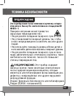
Page 77: ...77 0 II EN 60825 1 25249 6 65...

Page 78: ...78 10 C 50 C...

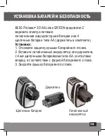
Page 79: ...79 883G Prolaser 3D All Lines GREEN 2 4 1 2 4 3...

Page 80: ...80 1 2 3 4 5 6 7 1 2 3 4 AA b 1 2 3 4...

Page 81: ...81 7 8 6 1 2 a d b c 3 4 5 1 2 a b c d 3 4 5 6 7 1 4 8 5 8...

Page 82: ...82 2 5 1 2 1 ON 360 b 3 a 4 a 5 a 6 a 7 2 5 8 1 OFF...

Page 83: ...83 1 1 OFF 2 a 3 b 3 4 a 5 a 6 a 7 a b 8 1 ON OFF...

Page 84: ...84 70 1 2 3 c d 4 5 a 6 c d...

Page 85: ...85 b...

Page 86: ...86 Kapro 1 2 3 4 5 1 1 A B C 5 2 0 5...

Page 87: ...87 A B Figure 1 C a1 0 5m c1 X 2m X approximately 5m 3 a 4 5 1 c1 1 5 0 5 1 2...

Page 88: ...88 6 180 B 2 a1 c1 7 b1 2 8 B 0 5 B 9 a 10 a1 b1 11 b2 3 A B Figure 2 C a1 0 5m c1 X 2m b1 X X 180 0 5 2 2...

Page 89: ...89 12 180 b2 a1 13 a2 4 A B Figure 3 C a1 0 5m X 2m b1 X b2 X 0 5 3 2 A B Figure 4 C a2 0 5m X 2m b1 X b2 X a1 X 180 0 5 4 2 14 a a2 a1 b b1 b2 15 a b 3...

Page 90: ...90 2 1 A B C 5 2 0 5 3 a 4 5 5 15 3 1 3 2 a1 5...

Page 91: ...91 a1 Figure 5 X approxim ately 3m 3 2 4 4 5 6 2 a1 6 5 3...

Page 92: ...92 a1 Figure 6 6 X 2m a2 X X 7 a1 a2 1 4 5 1 7 6 2...

Page 93: ...93 5 5 5 3 1 2 a 3 3 1 b1 c1 2 4 c2 7...

Page 94: ...94 c2 X c1 X X a1 2 5m 2 5m A b1 X B C Figure 7 5m 7 2 5 2 5 5 5 90 c1 a1 b1 6 c3 8...

Page 95: ...95 c3 X c1 X X a1 2 5m 2 5m A b1 X B C Figure 8 5m X c2 8 2 5 2 5 5 7 2 3 1 5...

Page 96: ...96 360 360 360 360 30 70 0 2 0 0002in in 2 5 2 0 5 5 515 525 II 2600mAh 7 4V 4 AA 8 10 C 50 C 20 C 60 C IP65 15 x 9 x 13 750 10...

Page 97: ...97 883G CEM 2014 30 EU 2014 35 EU 883G 2014 30 EU 2011 65 EU EN60825 1 2014 EN61326 1 2013...

Page 98: ...98...

Page 99: ...99...

Page 100: ...1 00 Rev 3 0 2020 Kapro Industries Ltd...

Reviews: