background image

This concludes the introduction to packet radio. The next chapter guides you

through the steps of installing your KPC-9612 Plus.

Introduction

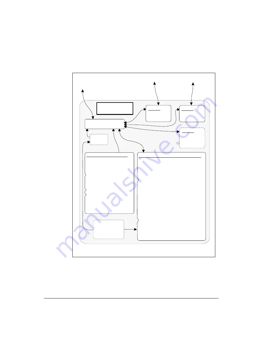
Inside a TNC – the KPC-9612 Plus

User’s Guide

28

KPC-9612 Plus v 8.2

Transceiver 2

Computer and/or

GPSdevice

KPC-9612 Plus Firm wa re.

Ka ntronic s softwa re,
store d in EPROM

* Prog ra m s to sup p ort

Inte rfa c e Mod e s

* Te xt for on-line he lp
* Prog ra m s to sup p ort

othe r func tions
(e. g . , KA-NODES)

"Ele c tric a lly Prog ra m m a b le
Re a d -Only Me m ory".

(i. e . , TERMINAL, NEWUSER, BBS,
KISS, XKISS, HOST,GPS & MODEM)

re a l-tim e
c loc k

RAM (Ra nd om Ac c e ss Me m ory).

The KPC-9612 Plus ship s with
128K
b e re p la c e d b y up to 512K of
RAM (e . g . to a c c om m od a te
a b ig g e r Ma ilb ox- PBBS).

* Me m ory use d for inte rna l

func tions (e . g . , storing
p a ra m e te r se tting s,
a sse m b ling a nd
d issa sse m b ling p a c ke ts,
storing d a ta from
p a c ke t c onne c tions,
KA-NODE sup p ort, a nd
storing GPS tra c king d a ta ).

* Ma ilb ox (PBBS) stora g e : De fa ult

RAM is 100K, use r-c onfig ura b le ,
within lim its of a va ila b le RAM.

* Pa g e Se rve r stora g e .

of RAM, whic h m a y

Inside the

KPC-9612 Plus

Mic ro-p roc e ssor

Lithium Ba tte ry:
p owe r b a c k-up,
for RAM a nd
re a l-tim e c loc k.

©

Cop yrig ht 1997 b y Ka ntronic s, Inc

Note : This d ia g ra m shows the m a jor c om p one nts of the KPC-9612 Plus.

The d ia g ra m is not to sc a le , nor is it a p a rts d ia g ra m .

Transceiver 1

Port 1:
low-sp e e d
m od e m

Port 3:
he a d e r
for a d d -on
d e vic e

Port 2:
hig h-sp e e d
m od e m

Summary of Contents for KPC-9612 Plus

Page 1: ...Reference and Hardware Specifications Kantronics 1202 E 23rd Street Lawrence Kansas 66046 Orders Inquiries 913 842 7745 FAX 913 842 2031 e mail sales kantronics com website www kantronics com Service...

Page 2: ...additional addendum sheets We solicit your comments and or suggested corrections Please send these to Kantronics Co Inc 1202 E 23rd Street Lawrence KS 66046 Copyright 1997 by Kantronics Co Inc All Ri...

Page 3: ...tronics in order for you to receive warranty service Refer to the warranty policy in this manual for further information Mail form and sales receipt to Kantronics 1202 E 23rd Street Lawrence KS 66046...

Page 4: ...User s Guide ii KPC 9612 Plus v 8 2...

Page 5: ...its Documentation are transferred from Kantronics to you 2 Term This License Agreement is effective until terminated You may termi nate this Agreement by destroying the PROM or diskette and documenta...

Page 6: ...provide you with upgrades of the SOFT WARE and or Documentation if you have provided Kantronics your completed Warranty registration with a copy of your receipt showing the amount you paid LICENSEE AC...

Page 7: ...2 Differences Between V 8 1 and V 8 2 of the KPC 9612 Plus 13 Major Uses of Your KPC 9612 Plus 13 Package Contents 14 Additional Parts For Your Packet Radio Station 14 Our Assumptions About You 15 Doc...

Page 8: ...erial Cable 39 Make Your Serial Cable 39 Installing the RS 232 Cable 42 Install Software and Configure Your KPC 9612 Plus 43 Port 1 Connect to a Transceiver 44 Parts for Connecting to a Transceiver 45...

Page 9: ...2 Pacterm Screens 73 The MAIN Menu Screen 73 The Terminal Screen 74 The Status Line 74 Pacterm Commands Overview 75 On Screen Help 75 From MAIN Menu BACKSPACE Go to Terminal Screen 75 From Terminal Sc...

Page 10: ...t Received Signal rtty ascii 88 ALT S n Speed Change 88 Trouble Shooting Difficulties in Communicating 89 Problem Go to Terminal Screen but Nothing Happens 89 Problem Your Computer Freezes Up 89 Probl...

Page 11: ...mand Mode 108 Connected vs Unproto 109 Monitoring and Calling CQ 109 A Simple Connect 110 Digipeating 111 Gateways 112 Multi Connects 112 Round Table Discussions 114 Selective Monitoring 114 Timing 11...

Page 12: ...l 128 SB cat 128 SP call 128 ST zip 128 Sending Messages 129 Listing Messages 130 Reading Messages 131 Editing Message Headers 132 E dit n BPTYNFH tocall fromcall BBS old new 132 Hierarchical Addresse...

Page 13: ...er 157 GPS NMEA Interfacing Capability 159 Overview 159 GPS Equipment Requirements 160 Cabling a GPS Unit to a Kantronics TNC 161 Setup Configuring a Kantronics TNC for GPS Operation 162 Setting Param...

Page 14: ...ign Stay 185 Help 185 Jheard Short Long 185 Nodes Short Long 186 Xconnect callsign 186 Other Modes of Operation 187 Remote Sensing and Control 187 Modem Mode 189 Copying Weather Broadcasts NWS EMWIN 1...

Page 15: ...ing to your Radios 287 Interfacing Hand Held Radios Port 1 only 288 Optional Connections to DB 9 Radio Port 290 Applying Power through the DB 9 connector 290 Resetting the KPC 9612 Plus through the DB...

Page 16: ...m Battery 304 Appendix D In Case of Difficulty 305 KPC 9612 Plus Does Not Sign On to Computer 305 You Are Unable to Make a Connect 306 Cannot Transmit 306 Cannot Return to Command Mode 307 Getting Out...

Page 17: ...anty Period it will at its option repair or replace the defective Ap plicable Product at no charge to you excluding in bound shipping charges 3 EXCLUSIVE REMEDY Repair or replacement of the Applicable...

Page 18: ...entation are sold to the consumer purchaser and become property of the purchaser Firmware and software are licensed for use by the consumer purchaser in return for a fee included in the purchase price...

Page 19: ...tions contained in any software will meet your requirements or achieve your intended results or that operation of any software will be uninterrupted or error free or without effect upon other software...

Page 20: ...Warranty Registration card and copy of proof of purchase establishing purchase date 8 NON ASSIGNMENT This Limited Warranty is not assignable by you Any attempt to assign or transfer any of the rights...

Page 21: ...the Kantronics wiring instructions in this manual Verify your terminal baud rate It may be useful to perform a Hard Reset See Hard Reset section If service or repairs still appear necessary after you...

Page 22: ...used and if possible a list of current parameter values for your unit as shown in a DIS PLAY listing Be sure to include a return fax number and or e mail address Returns to the factory for refund or e...

Page 23: ...try fees whether the return is for warranty or non warranty repair Usually the best way to return items to us is by mail However if you wish to use one of the courier services such as DHL UPS Expedite...

Page 24: ...to any conversations with the technical sales staff about the problem and the Return Authorization number assigned For warranty repairs we will pay the shipping charges to return the item s to you via...

Page 25: ...evision reception which can be determined by turning the equipment off and on the user is encouraged to try to correct the interference by one or more of the following measures Reorient or relocate th...

Page 26: ...l RF environment and may be causative factors in RFI induced problems The suggestions given here may assist in resolving RFI problems you may encounter in your unique station Use shielded cable for al...

Page 27: ...uction to packet radio Installing and configuring your KPC 9612 Plus packet radio station and making your first connections Documentation for Pacterm the PC terminal software shipped with the KPC 9612...

Page 28: ...za tion in the 9612 have been replaced with digital pots These new pots are con trolled with commands titled transmit level XMITLVL and equalize EQUALIZE XMITLVL is a dual port command and is convenie...

Page 29: ...d UIGATE These com mands may be useful for other activities too No version 8 1 commands were deleted See the command descriptions for details Major Uses of Your KPC 9612 Plus Adding the KPC 9612 Plus...

Page 30: ...5 DS HD 1 44MB formatted for PC IBM compatible computers which includes a PC terminal program Warranty registration form see front of this manual and of course this User s Guide manual Additional Par...

Page 31: ...ress the ENTER key Sometimes you will need to hold down one key on the computer while pressing another key This is indicated by giving the name of the first key then a plus then the name of the second...

Page 32: ...You will get more out of packet radio and have an easier time get ting started if you have at least a basic understanding of what is involved in packet radio communication Do not be concerned here wit...

Page 33: ...s digitally with your computer Multi port TNCs e g Kantronics KPC 9612 Plus can support more than one transceiver at once The computer communicates digitally with the TNC so you can 1 view messages re...

Page 34: ...essage from the time it is created by W XI to when it is read by KB NYK Step 1 Before this message can be transmitted from a source station to a destination station via an intermediate sta tion all th...

Page 35: ...is processed by W XI s TNC the TNC assumes that the operator wants to begin sending messages So the TNC 1 puts a mes sage on the computer monitor confirming that W XI is now connected through intermed...

Page 36: ...e the AX 25 standard but it is possible to use another standard or pro tocol e g TCP IP on top of AX 25 in which case the packet is referred to by the name of the highest level pro tocol Step 7 After...

Page 37: ...of 1 s and 0 s in the incoming bit stream and identifies the burst as an AX 25 packet of information containing the message HELLO Also and most significantly N GRG registers that the packet designate...

Page 38: ...t addressed to it Since the digipeated packet originally came from KB NYK to whom he is connected and since the packet contains an acknowledgment for data that he had recently sent W XI s TNC can rest...

Page 39: ...back and forth coordination with any receiving station Stations receiving these packets can check to see if the packets are correct i e the same bit pattern is re ceived as when they were sent but th...

Page 40: ...arties or until the sender times out after trying a number of times to get feedback and not succeeding Hint In most cases communication by packet radio is like mail not the tele phone in that it is no...

Page 41: ...col Now it is useful to give a brief discussion of this protocol and another that fits within it Overview of Packet Radio Introduction KPC 9612 Plus v 8 2 25 User s Guide An AX 25 information packet a...

Page 42: ...r Protocol Hint You can set the KPC 9612 Plus to use an earlier protocol AX 25 level 2 version 1 Alternatives to AX 25 TCP IP and the KISS protocol The TCP IP Transmission Control Proto col Internet P...

Page 43: ...o has developed more and more features have been added within TNCs including memory and software dedicated to a Personal Bulletin Board System and in some TNCs support for paging Also multi port TNCs...

Page 44: ...la c ed by up to 512K of RAM e g to a c c om m oda te a big g er Ma ilbox PBBS Mem ory used for interna l func tions e g storing pa ra m eter setting s a ssem bling a nd dissa ssem bling pa c kets sto...

Page 45: ...r documentation The major steps involved in installing i e connecting the parts your packet ra dio station are as follows connect your KPC 9612 Plus to a power source and confirm that the unit powers...

Page 46: ...ctions between components that will be involved in the installation of your station The KPC 9612 Plus Your KPC 9612 Plus is going to be at the center of your packet radio station so setting up your st...

Page 47: ...KPC 9612 Plus via radio without using your computer And your KPC 9612 Plus can serve as a radio relay station for other sta tions without your computer being connected This independence from the com p...

Page 48: ...ble XT or above Operating System MS DOS or PC DOS version 3 3 or higher RAM Random Access Memory A minimum of 384 K Disk drives A 3 5 High Density 1 44MB floppy drive Hard drive optional You do not ne...

Page 49: ...Plus For example Kantronics Host Master II offers significantly more functionality than does the start up program Note Users of Windows 3 1 or above have another alternative The Win dows Accessories...

Page 50: ...s as an external modem not as a TNC a less familiar term GPS Device Optional The KPC 9612 Plus works with Global Positioning System GPS devices that 1 support the NMEA 0183 standard and 2 have a datap...

Page 51: ...y step instructions for installing your station which we will do in the following order the two different ways you can power the KPC 9612 Plus How the Parts of Your Station are Connected KPC 9612 Plus...

Page 52: ...station needs to be set up both in terms of hardware and software Connect Your KPC 9612 Plus to a Power Source As illustrated on the right side of the station cabling diagram on page 35 there are two...

Page 53: ...onnector of the KPC 9612 Plus Step 3 1 Turn ON the power supply 2 press the power switch on the front panel of the KPC 9612 Plus to turn your KPC 9612 Plus ON 3 confirm that the power in dicator next...

Page 54: ...y Step 2 Connect the 2 1 mm connector on the assembly to the power connector of the KPC 9612 Plus and plug the power adaptor into the 120Vac power source being sure that the center is positive Step 3...

Page 55: ...rchase Your Serial Cable To purchase your cable from your local amateur radio dealer or computer dealer specify that you need a standard serial modem cable RS 232C with high quality shielding of whate...

Page 56: ...third party software does not use hardware flow contol and therefore does not need the RTS and CTS wires shown below For details on preparing your cable wiring use the chart below that is appropriate...

Page 57: ...DCD 20 20 DTR CASE 2 A Wiring if computer has a 9 pin connector and the cable has 5 wires 2 3 TXD 3 2 RXD 4 7 RTS 5 8 CTS 7 5 SG CASE 2 B Wiring if computer has a 9 pin connector and the cable has 8...

Page 58: ...the RS 232 Cable Once you have purchased or made your serial communication cable connect it as follows Step 1 Make sure that power to both your computer and your KPC 9612 Plus is turned OFF Step 2 Plu...

Page 59: ...s serial port but an ad vanced user can change jumpers so that it does If your KPC 9612 Plus has been altered to apply 12 Vdc to pin 13 of the computer serial port this can DAMAGE your computer if pin...

Page 60: ...e 64 The Pacterm chapter includes all the steps needed for installing the software and using it to configure your KPC 9612 Plus It also will serve as your Pacterm manual as you continue using the soft...

Page 61: ...612 Plus are attached to this DB 9 connector actually the wires in the cables are at tached to specified pins on the cable assembly s DB 9 connector One cable con tains wires connecting the KPC 9612 P...

Page 62: ...bly This section gives instructions for how to assemble the cable assembly needed to connect your transceiver to your KPC 9612 Plus starting with the wiring require ments Wiring Directions Connecting...

Page 63: ...male connector for the KPC 9612 Plus s Radio port 1 and transceiv ers including HTs from three major manufacturers Yaesu Icom and Kenwood These diagrams may also apply to transceivers from other manuf...

Page 64: ...Icom diagrams page G9 Installing Your KPC 9612 Plus Port 1 Connect to a Transceiver User s Guide 48 KPC 9612 Plus v 8 2...

Page 65: ...Kenwood diagrams page G10 Port 1 Connect to a Transceiver Installing Your KPC 9612 Plus KPC 9612 Plus v 8 2 49 User s Guide...

Page 66: ...of the following connec tions which you will use for wiring your assembly identify and make a note of the connector to the tip of your external speaker plug which will be wired to pin 5 receive audio...

Page 67: ...nsceiver cable assembly proceed as follows Wiring between your Transceiver Microphone and your KPC 9612 Plus Follow the notes taken above and wire the cable assembly in the following order Step 1 Sele...

Page 68: ...tach the wire from pin 9 one path to ground on the DB 9 to the ground pin on the microphone con nector Connecting your Transceiver s Speaker Plug to Your KPC 9612 Plus Use the speaker plug cable suppl...

Page 69: ...s of the assembly use one of the screws to connect the two brackets passing the screw through the hole on the thin side of one bracket and attaching it screwing it into the threads to the other bracke...

Page 70: ...ctor into the slot at the wide end of the shell with pins facing away from the shell and cables resting inside the shell with the backplane of the DB 9 connector fitting behind the lip that protrudes...

Page 71: ...e connected Connecting Your Transceiver Cable Assembly Now you are ready to use this cable assembly to finish assembling your packet radio station Step 1 Check to be sure all the parts of your complet...

Page 72: ...y counter clockwise Step 6 Slowly turn the transceiver s receive volume up until the RCV LED receive indicator on the KPC 9612 Plus lights up turns ON Step 7 Increase the transceiver s receive volume...

Page 73: ...and You should adjust the drive level to provide about 3 to 3 5 kHz of deviation with your radio If you don t have access to a deviation meter adjust drive so your packet transmissions generate about...

Page 74: ...panel In order to trans mit and receive at high speed you must connect the following pins to your radio paste in DB 15 connector diagram top 8 1 bottom 15 to 9 DB 15 The pin assignments for the DB 15...

Page 75: ...anual You may then have to adjust the level using the XMITLVL command until you achieve acceptable performance HINT If you have an existing 9600 baud node or other station operating in your area that...

Page 76: ...0 baud modem is de coding the received signal This indication is more accurate than using the eye pattern method used with the G3RUH modems See the Calibration Equal ization section later in this manu...

Page 77: ...PC 9612 Plus You will need to purchase or make a cable us ing the specifications in your GPS manual To connect the GPS receiver and the KPC 9612 Plus as a Stand alone position reporting system without...

Page 78: ...Installing Your KPC 9612 Plus User s Guide 62 KPC 9612 Plus v 8 2...

Page 79: ...perate with a wide range of terminal communication programs including the TERMINAL communication program that comes with Microsoft Windows Some of these other communication programs offer more functio...

Page 80: ...rectly to DOS Other uses of Pacterm are as follows SEND a file from your computer to your TNC for transmission Switch the TNC at any time into Command Mode making it ready to accept commands instead o...

Page 81: ...reen to control the session and communicate with the TNC 6 If you get the Pacterm Cannot Communicate screen the first time you try to go to the TERMINAL Screen be sure the TNC is turned ON and or pres...

Page 82: ...opying files from a floppy to your hard drive You may install Pacterm on your hard drive by simply copying the Pacterm program file to the drive and directory or subdirectory of your choice as follows...

Page 83: ...ive to which you want Pacterm copied e g C which can be any drive except the floppy drive with the Kantronics Program and Information disk it it that has the space for it 4 Next type and enter the dir...

Page 84: ...g cable is plugged in securely There are no other faults in the normal operations of the components or connections between them When you first try to communicate with the TNC Pacterm checks for a sig...

Page 85: ...directory from which you start Pacterm For example suppose the program PACTERM COM is in C COMM i e drive C directory COMM and you are on directory SAVEBUFF on a disk in drive A A SAVEBUFF In this cas...

Page 86: ...nation 3 When the AUTOBAUD routine receives the character from the serial port it uses that character to determine Pacterm s BAUD rate 4 AUTOBAUD then sets the TNC s BAUD rate to match Pacterm s BAUD...

Page 87: ...term Required TNC Parameter Settings To work with Pacterm the following TNC parameter settings are needed COMMAND 03 CTRL C default 03 so unless this has been changed you do not need to do anything Hi...

Page 88: ...l note XFLOW controls whether or not software flow control is ON If XFLOW is set to OFF the following parameters should also be set to 0 zero XON XOFF START and STOP FILTER OFF default 8BITCONV ON def...

Page 89: ...ibed on the MAIN Menu except SETUP functions and ESC The MAIN Menu Screen As shown below the MAIN Menu screen shows all the functions available in Pacterm and serves as a Help screen as well Each MAIN...

Page 90: ...hold data to send it later OFLIN Shows whether the user has set Pacterm to request the TNC to send data START or not to send data STOP The current status of Output Control Functions If the PRINT reque...

Page 91: ...rt and BAUD rate are set up as you need MAIN Menu keys except those used for SETUP or for EXIT to DOS can also be used to go to the Terminal Screen From Terminal Screen F1 Go to MAIN Menu After you SE...

Page 92: ...session F3 Select TNC Use Default Packet Pressing F3 switches back and forth between two uses of your TNC with Packet communication default or with HF Non Packet communication The current setting for...

Page 93: ...ly the same as bits per second Press F8 to step through the available baud rates Pacterm s current BAUD rate is shown on the MAIN Menu Since data flows back and forth between Pacterm and your TNC both...

Page 94: ...rol signal is shown on the right end of the status line RTS is shown if RTS is ON CTS is shown if CTS is ON F5 Pacterm to TNC Offline or Online Default Pressing F5 from either the MAIN Menu or the Ter...

Page 95: ...at try to connect The status of this command START or STOP is shown on the Status Line Technical note START is a request for the TNC to send any new data to Pacterm Before new data will actually be se...

Page 96: ...res you may get print outs by copying material to the Holding Buffer saving it as a file then using any text editor or word processor to bring in the ASCII file and print it Caution Using ALT P to tur...

Page 97: ...Holding Buffer before you use this command F2 Holding Buffer SAVE and CLEAR Press F2 to SAVE the current contents of the Holding Buffer to a file in the cur rent directory or to the current directory...

Page 98: ...to save the file or if the drive door is open you will get the standard DOS message Not ready reading drive n Abort Retry Fail If you can fix the problem e g shut the door or insert a disk with enoug...

Page 99: ...our computer to your TNC which is then responsible for sending it on to your transceiver for transmission 1 Use Pacterm to put your TNC in either Conversation Mode or Transparent Mode connection with...

Page 100: ...send such a file successfully add an EOF code e g by using an appropriate word pro cessor Commands Exiting The following exit commands are available in Pacterm F9 Switch Your TNC to Command Mode From...

Page 101: ...Pacterm session Hint If your TNC is turned OFF when you press F10 your computer may freeze up when these commands are sent by Pacterm Try turning the TNC back ON and using F10 again to EXIT If there...

Page 102: ...the keyboard Commands that Work Differently in HF Non Packet Mode When Pacterm is in HF non packet mode the following commands have an X added to the string of characters they send to the TNC F9 Go to...

Page 103: ...This command can be used with all the HF Non Packet modes listed above ALT R sends a CTRL C R sequence to the TNC This will immediately return the TNC to the receive mode even if there is still data...

Page 104: ...ASCII and CW ALT S n sends a CTRL C n sequence to the TNC where n is a number from 0 to 9 This command lets you change the speed at which you will transmit in RTTY ASCII or CW modes In RTTY or ASCII m...

Page 105: ...n the current COM port e g a mouse or an internal phone modem So if the device on the current COM port is not a TNC Pacterm will be running under a misunderstanding and in this case your computer may...

Page 106: ...response garbled data or partially garbled data may indicate the TNC has been switched to HOST or KISS mode and needs to be switched back to NEWUSER or TERMINAL See the TNC doc umentation for instruct...

Page 107: ...iar with other communication software you may use it in stead of Pacterm In this case you need to be aware that Kantronics documenta tion and support services assume the use of Pacterm at least for ge...

Page 108: ...r TNC ha s a t lea st one una c knowledg ed pa c ket on the c urrent strea m i e a pa c ket tha t wa s tra nsmitted to a nother sta tion ha s not been a c knowledg ed or a pa c ket is c ued for tra ns...

Page 109: ...nd displayed on your computer screen such as the following KANTRONICS PACKET CONTROLLER 9612 PLUS VERSION 8 1 C COPYRIGHT 1988 1997 BY KANTRONICS INC ALL RIGHTS RESERVED DUPLICATION PROHIBITED WITHOUT...

Page 110: ...sation mode the KPC 9612 will interpret data re ceived from Pacterm or any other source as data to transmit In CONVERS mode the KPC 9612 Plus interprets most characters as information to be trans mitt...

Page 111: ...described in the next section the TRANS command is not a NEWUSER command To get out of TRANS mode and back to COMMAND mode enter Ctrl C three times with a pause of less than one second between each e...

Page 112: ...SS XKISS GPS or MODEM Default is NEWUSER which makes available just the basic commands listed here Configure your TNC RESET MYCALL DAYTIME TXDELAY DWAIT Restart the modem equivalent to turning your TN...

Page 113: ...posed to insure that digipeaters have priority access to the radio frequency ECHO When ON characters you type on the keyboard will be echoed back to your terminal When OFF characters you type will not...

Page 114: ...continue on your own using KPC 9612 Plus commands Check Your KPC 9612 Plus s Version Number and ID To check your KPC 9612 Plus s version number and ID all you need to do is ask to see the current sett...

Page 115: ...essage consisting of the name of the command and the value s of it s param eters for display on your monitor For example if you type INTFACE you will see INTFACE NEWUSER if you are currently in the NE...

Page 116: ...t part of your KPC 9612 Plus is to simply connect to your own personal mailbox built in to the KPC 9612 Plus This is an internal connect so your radio does not need to be connected to do it Step 1 Go...

Page 117: ...then the standard mailbox prompt ENTER COMMAND B J K L R S or Help Step 5 Now disconnect just like you will disconnect from any other user First return to command mode by typing a Ctrl C on your keybo...

Page 118: ...actual message that was sent In the example N KN is the transmitting station and KB NYK is the receiving station You may see the RCV LED light at times indi cating a signal is being received but noth...

Page 119: ...rs that must be used For instance if you need to use two digipeaters with callsigns of W XI and N GRG in order to connect to KB NYK you would give the connect command as CON NECT KB NYK VIA W XI N GRG...

Page 120: ...ow you are on port 2 channel a From here issue a connect command such as cmd C W XI and carry on a communication with station W XI Step 3 To disconnect and remain on Port 2 issue the disconnect comman...

Page 121: ...just these basics you can do a lot but you have a great deal more power if you want to ex plore the full possibilities For more information on all the topics we have covered here and more see the foll...

Page 122: ...Getting Started Other Topics User s Guide 106 KPC 9612 Plus v 8 2...

Page 123: ...troductory chapter on how packet radio uses digital information for communication By familiarizing your self with the concepts presented here you ll be aware of and if you wish able to change the defa...

Page 124: ...adio AX 25 The most commonly used protocol in amateur packet radio is AX 25 The details of the inner workings can be found in a book titled AX 25 Amateur Packet Radio Link Layer Protocol which is avai...

Page 125: ...for informal roundtable chats Monitoring and Calling CQ If you turn the MONITOR command ON you will see other people s packets on your screen You will notice two callsigns at the beginning of each pac...

Page 126: ...d what the person connected to you sends you Any pack ets sent by other people will not be monitored unless they are also connected to you on another stream Two things determine when the data you send...

Page 127: ...ust the from and to stations of the monitored packets We will also see the callsigns of those stations that have been used as digipeaters This list of stations is often called a path Here is an exampl...

Page 128: ...commands For a description of Kantronics UI digipeating commands see Advanced GPS APRS digipeating in the GPS Mode of Operation section of this chapter Gateways In Kantronics multi port devices e g K...

Page 129: ...ter key is necessary Note Kantronics most recent multi port TNCs e g KPC 9612 Plus use only one stream switch character and a number to specify which port and which stream to switch to See example bel...

Page 130: ...e and Slottime When the TNC acts as a digipeater packets received that need to be relayed are retransmitted as soon as the frequency is clear Other TNCs on frequency should hold off or wait their turn...

Page 131: ...ess than the PERSIST value we now start the key up of the transmitter to send the packet Txdelay TXDELAY should be adjusted to allow your radio sufficient time to switch from receive mode to transmit...

Page 132: ...e number reused in the same transmission This is also true for Version 2 If the first acknowledgment is received there is really no difference between the two versions practically speaking The differe...

Page 133: ...l an outstanding packet of information This is the major difference between version 1 and version 2 The connect attempts would then continue for the number of retries set in the TNC and if no response...

Page 134: ...d likewise if there is a Ctrl S in a file being sent data flow from the TNC will stop until a Ctrl Q is received XFLOW needs to be turned ON for the TNC to use software flow control XOFF determines th...

Page 135: ...e When it is pulled low it knows to stop sending data When the line is again pulled high by the TNC the computer program will restart sending data On the other hand the computer holds RTS high as long...

Page 136: ...allow for local echoing to the screen while uploading Getting Out of Transparent Getting into the Transparent Mode is easy you just type a t in Command Mode But since Transparent Mode allows the send...

Page 137: ...XYZREM If these two parameters are not set remote access to the command set of this TNC is not possible When these parameters are set you can connect to the MYREMOTE callsign of the remote TNC When th...

Page 138: ...ike CONNECT W1ABC the remote TNC will indeed connect to the station but there will be no data sent to you from that connection The connected data would be sent to the serial port of that remote TNC We...

Page 139: ...mailbox is compatible with the large community bulletin board sys tems RLI MBL etc and will allow them to forward mail for you directly into your TNC You may also place messages in your mailbox and i...

Page 140: ...command Let s assume you want to send a message to KB NYK You would now use the Send Private command SP KB NYK and the TNC responds with SUBJECT Now enter a short subject line Just a quick question T...

Page 141: ...connecting directly are as follows B ye This command is entered by the PBBS user to disconnect from the PBBS E dit n BPTYNFH tocall fromcall BBS old new This command is available only to the system o...

Page 142: ...s of the messages if any L ist call Allows you to list only those messages in the mailbox which are addressed to a specific callsign or which were sent by a specific callsign To list only those messag...

Page 143: ...he PBBS K ill n Deletes message number n from the mailbox You may only delete TRAFFIC messages PRIVATE messages addressed TO or FROM you or BULLETINS you sent The SYSOP may delete any message includin...

Page 144: ...ot already read S end call Sends a PRIVATE message to the callsign specified Using S end is the same as using the SP command SB cat The SB Send Bulletin command is used to send a BULLETIN to the PBBS...

Page 145: ...TRAFFIC this should be NTSxx where xx is the two letter POSTAL code for the state mid is the MESSAGE ID assigned to the message by the originator bid is the BULLETIN ID assigned to the message by the...

Page 146: ...or warded until the SYSOP has edited the message header and changed the H flag This gives the SYSOP full control over the messages relayed by his station Messages entered from the local keyboard conne...

Page 147: ...owing status characters in the sec ond position H This is a personal message that has an BBS field but is being held for review by the SYSOP before it may be forwarded N This message is a Personal mes...

Page 148: ...tled Remote Sysop Access to your PBBS for more detail The TYPE of the message B Bulletin P Private T Traffic The STATUS of the message Y Yes it has been read N No it has not been read F Forwarded it h...

Page 149: ...e the SYSOP command the PBBS will send you a password verification string which must be properly responded to in order to gain SYSOP access This is ex plained in detail later Let s say you want to edi...

Page 150: ...rchical address con tact your local packet BBS sysop and ask what the proper addressing is for your location The PHEARD command will show you the callsigns of stations recently connect ing to your mai...

Page 151: ...o be sent to a user who connects to your PBBS by using the PTEXT command This command accepts up to 128 charac ters as a text string to be sent to the user immediately after the SID is sent If it beco...

Page 152: ...SYSOP Access to the PBBS You can gain remote SYSOP access to your PBBS e g to edit messages using the EDIT command by first connecting to your PBBS and then entering the SYSOP command When you enter t...

Page 153: ...ge The next several fields separated by periods are the state two letter postal abbreviation coun try and continent In this case since Texas is so large it is sub divided into smaller areas These are...

Page 154: ...S Date Time Subject 59765 B 1491 NASA N5IST ALLUS 1004 1529 GALILEO STATUS 09 30 93 59764 BNL 468 WX N0NEJ 1012 1017 KC Forecast 10 12 400am 59763 BNL 659 WX N0NEJ 1012 1017 MO Forecast 10 12 400am 59...

Page 155: ...see the complete information BBS systems allow a sec ond version of the READ command RH or V that will display more routing in formation A routing list from a bulletin appears below R 931012 1107 2726...

Page 156: ...BBS That BBS will then address the message to you using the BBS and hierarchical routing information in the last R line of the message you sent A user may also simply use the send private command SP...

Page 157: ...le EVERY BBS in West Texas would have to know how to send messages to your callsign not just to your HOME BBS One solution to this is to include the callsign of your HOME BBS as part of your HTEXT Thi...

Page 158: ...ing any terminal program e g Pacterm Other amateurs may send pages using your system by connecting to the TNC in packet mode Like your PBBS mailbox the Page Server will prompt the user for pager addre...

Page 159: ...s they are capable of receiving numbers and a limited number of special characters Even so with these devices a call back may not be necessary if the parties have agreed that certain numbers have spe...

Page 160: ...ntrol the transmitters spread out across the city and manage the paging system as a whole With inter city paging so called wide area paging paging network controllers handle the job of exchanging page...

Page 161: ...We ll con tinue to refer to the RPC1 as POCSAG This protocol for sending paging mes sages is today s defacto standard and its details are presented in Anderson s Paging Handbook for the Radio Amateur...

Page 162: ...00 data ready transceivers made for packet radio operation are capable of transmitting and receiving POCSAG pages Fourth selected Kantronics TNCs include POCSAG decoding The following diagram shows th...

Page 163: ...a good encoder choice for several reasons it may be located remotely sending pages can be supported via a packet connect without a computer present via the Paging Server and the 9600 baud integrated...

Page 164: ...old today may be suitable for amateur use The key is to find those that can be converted for 2 meter or 70 cm use Some of Motorola s Bravo and Bravo Plus series of 150 and 450 MHz pagers can be con ve...

Page 165: ...alternatively the CAL calibrate command Equalization of the receive circuit of a radio used for page monitoring accom plished within the TNC is usually not necessary if discriminator audio is avail ab...

Page 166: ...maining and most used commands are PAGE and PAGEMON Briefly the PAGE command is used to send a page and includes the following parameters format baud rate pager address capcode and message For exam pl...

Page 167: ...3 denotes the function code in the page e g decoding to standard 3 is alpha and the date and time shown in brackets are optional added at the time of reception if MSTAMP is ON Paging Modes of Operati...

Page 168: ...G logs all pages sent PAGEMON enables page monitoring PAGEPRIV sets a flag to limit access to the directory log PAGEPSWD controls password access PAGETEXT establishes a sign on message PAGEXINV invert...

Page 169: ...d PAGE 111222 8427745 or alternatively cmd PAGE N 1200 111222 8427745 Note that there are spaces between the parameter entries Example 2 Now let s page Don N GRG to call the office assuming that his c...

Page 170: ...alternatively cmd PAGED N GRG Don A 2400 111333 Now let s make an entry for W XI s 1200 numeric pager cmd PAGED W XI Phil 111222 To delete these entries from the directory use the PAGEDIR command agai...

Page 171: ...mmand Reference The PAGELOG command allocates n Kbytes of memory for the log Allocating memory i e using the numeric parameter will cause the TNC to reset To clear the log but retain the memory alloca...

Page 172: ...e and normally state 3 both bits a 1 indicates an alphanumeric page The TNC uses these fuction bits to decide how to decode the page e g as nu meric or alphanumeric The TNC sends all numeric pages wit...

Page 173: ...port 1 or port 2 using the callsign set by MYPAGE If PAGEMON is ON the TNC will not support packet connects on the high speed port Like the mailbox users may select from a list of command options show...

Page 174: ...user are ready to send a page list the page direc tory list the pagelog or disconnect from the PS For example suppose that you wish to send a page to Phil see page directory en try example earlier Yo...

Page 175: ...ed at the end of the page log data To leave the Page Server at this point simply enter the BYE command B and hit return as follows B This concludes the Paging section of the Modes of Operation Paging...

Page 176: ...port collect this positional information and use it to compute position This information can then be retransmitted by any means possible to report the position of the GPS unit and its vehicle Most GP...

Page 177: ...the infor mation and if desired transmit that location via a packet unit using unproto packets The TNC may receive the NMEA information directly hence it may be combined with a GPS unit alone to broa...

Page 178: ...devices see the Kantronics Limited Warranty To connect the data port of a GPS unit to your TNC you ll need a three wire ca ble A shielded cable is preferred Refer to your GPS manual to determine whic...

Page 179: ...t LT buffers by entering the string header with the GPSHEAD command The TNC searches for specific strings of data from the GPS unit and stores them in up to four LT buffers These LT buffers may then b...

Page 180: ...ring to be stored For instance if you want the TNC to store the GPGGA string in LT buffer num ber 1 use the command GPSHEAD 1 GPGGA In order to beacon an LT buffer you must set the LTP and the BLT com...

Page 181: ...ers for initial ization before they will send any information You can tell your TNC to send the initialization string to your GPS unit by entering the required string using the GPSINIT command For ins...

Page 182: ...e BLT command provides for the ability to specify not only the interval be tween beacons but a starting time for the beacons This permits a slotted sys tem of beacons by numerous stations For instance...

Page 183: ...the TNC commands however there are two options 1 exit the GPS Mode using a terminal or 2 connect to the TNC remotely by radio MYREMOTE and change the commands When you connect remotely to the TNC and...

Page 184: ...g GPS commands are listed here for convenience and explained in detail in the Command Reference section BLT n EVERY AFTER hh mm ss START hh mm ss n 1 4 This command sets the interval between beacons f...

Page 185: ...racters This is an immediate command which sends the text string from the serial port of the TNC to the attached device e g GPS unit Also see the GPS setting for the INTFACE command When this command...

Page 186: ...Of course this requires the acceptance and use of standards for naming and using digipeating stations by both the position re porting stations and the digipeating stations Common standards have been e...

Page 187: ...below and the command description for more detail UIFLOOD and UITRACE are a bit more exotic Each provides for multi hop digipeating with just one digipeater address per packet thereby keeping the tra...

Page 188: ...m consisting of one po sition reporting station and three digipeaters where each digi is configured using the UIDIGI UIFLOOD or UITRACE command and where UIDWAIT is set ON We set UIDWAIT ON to force t...

Page 189: ...A C B UI 5 N GRG GPS C A B UI 5 N GRG GPS C B A UI 5 All digis hear the first UI frame and store it Due to the setting of UIDWAIT some stations may wait longer than others to digipeat hence when they...

Page 190: ...ed and decremented field of WIDE4 3 Note that each digi hears the UI frames repeated by the others but does not digipeat those in turn since a timeout of 30 seconds was specified by the UIFLOOD comman...

Page 191: ...s noted Configuring Digis for HF VHF Gateway Operations This example assumes the use of at least one multi port TNC that supports both HF and VHF operation In this example we demonstrate cross band ga...

Page 192: ...n C hears station D s repeat of the frame and digipeats the frame decrementing flood to FLOOD4 2 It didn t digipeat its own FLOOD4 4 frame because it can t hear itself Station B fin ishes last due to...

Page 193: ...Mobile Radio Technology February 1994 Kaplan Elliot The global positioning system GPS Communications Quarterly Sum mer 1994 Langley R The mathematics of GPS GPS World Magazine July August 1991 NMEA 01...

Page 194: ...d node At the same time KA Nodes are useful in that they are more efficient than digipeaters in using channel time while not requiring the effort and time required to maintain a full node When packet...

Page 195: ...ake care of it The following material is provided to assist you in configuring your KA Node and telling others how to connect to and use it A listing of the node commands for users follows Configuring...

Page 196: ...e material that follows is meant for those using your KA Node i e connecting to it You may use this material as a guide to using someone else s node or in connecting to your own node from another loca...

Page 197: ...ad heard nothing it would respond with NO KNOWN NODES You may instead wish to know what other stations the KA Node has heard lately This would be accomplished by sending a J for the JHEARD command The...

Page 198: ...and and must be spelled out entirely For instance if you tell the KA Node C KB5EEG and then decide to abort the connect your next entry must be ABORT Any other entry will cancel any possible abort of...

Page 199: ...age from the KA Node saying DISCON NECTED BY call AT NODE MYNODE In other words if you connected from Lawrence Kansas to a KA Node in Lincoln Nebraska and then told that KA Node to connect to someone...

Page 200: ...knowledgment of packets For example suppose you just connected to node LAWKAN and wish to cross connect to N GRG whose station is tuned to the frequency of the other port of the node Just issue X N GR...

Page 201: ...ll appears in the JHEARD list to the port indicated for other stations you can determine whether to CONNECT or XCONNECT to the station of your choice KA Node Commands for Remote Use When accessed by r...

Page 202: ...isconnect Help Causes the KA Node to send a brief help list showing all commands available with the options and a short description of each command Jheard Short Long Causes the KA Node to transmit its...

Page 203: ...the same list without dates and times The long JHEARD L version of this command will also show the destination field and any digipeaters used Nodes Short Long Causes the node to return a list of KA N...

Page 204: ...r and additional circuitry that converts the analog voltage presented at two specified inputs into digital values from 0 to 255 You can then use these digital values reported in binary as an approxima...

Page 205: ...details needed to adapt these broad capacities to your own situation with your own sensors controls and remote locations Other Modes of Operation Modes of Operation KPC 9612 Plus v 8 2 189 User s Guid...

Page 206: ...if a full RS 232 cable is used This can occur because the RS232 CD line which is tied to the TNC s receive LED may be cycling up and down In this case set CD to EXTERNAL before entering INT MODEM Cop...

Page 207: ...switch out of HOST mode is to use your host mode software see instructions with that software If you begin using Pacterm while the TNC is in HOST mode you will see the message S sent by the TNC to in...

Page 208: ...onverts the packets of synchronous data being received from the radio link into packets of asynchronous data to be passed to the computer over the serial port and converts the packets of asynchronous...

Page 209: ...3 and 4 pp 4 62 4 68 ARRL Amateur Radio Computer Networking Conferences 1 4 Newington CT ARRL 1985 Chepponis M and Karn P The KISS TNC A Simple Host to TNC Communications Protocol pp 38 42 6th Compute...

Page 210: ...transmissions from all stations connected to the node By local agreement users do not connect directly to each other they connect only through the master DAMA was developed in Germany by NORD LINK Ref...

Page 211: ...are connected to each other using a standard NET ROM type protocol For the DAMA system to work effectively each slave associates with only one master node and connects only to that master If an end us...

Page 212: ...lution Proceedings of the 14th Computer Networking Conference American Radio Relay League Newington CT USA 06111 Rech Wolf Henning N1EOW DF9IC and Kneip Johannes DG3RBU The German Central Eu ropean Pa...

Page 213: ...as tested with TheNetNode firm ware Version 1 56 TFKISS Version 2 0 and by volunteer testers in Europe with firmware used in existing DAMA networks Kantronics cannot be responsible for subsequent chan...

Page 214: ......

Page 215: ...d how port 2 may be used These are called multi port commands An important feature of the KPC 9612 Plus multi port design is that the device can be expanded to be a three port TNC by simply installing...

Page 216: ...definition shows the syntax for entering the com mand beginning with the name of the command followed by a listing of any pa rameters that may be used with the command The full name of each command is...

Page 217: ...he parameter n are defined as n 1 255 Unless otherwise noted a forward slash is used to separate parameters en tered for port 1 from parameters entered for port 2 For example parameter val ues entered...

Page 218: ...iption These are deci mal numbers n 00 FF Special functions Some parameters are used to control special functions such as specifying the character to use to enter the Command mode from the Convers mod...

Page 219: ...values in decimal or precede the with the PASS character in order to enter hex numbers flags ChoiceA ChoiceB Many parameters are flags meaning they have two possible values ON and OFF or YES and NO A...

Page 220: ...t for Command Mode is cmd Hint Once you go into Packet Convers Mode a Ctrl C see COM MAND needs to be entered to return you to the Command Mode In the Packet Transparent Mode or GPS Mode a special seq...

Page 221: ...er the short form of a command name the charac ters underlined in the listing The short form is not necessarily the shortest unique string in the name or the first match in alphabetical order rather i...

Page 222: ...s the baud rate used for input and output through the serial RS232 port of the TNC to a computer If 0 is used the TNC will run an autobaud routine upon power up This routine looks for an asterisk char...

Page 223: ...number in the range of 0 255 for each line at the RS 232 port Each decimal value corresponds to a voltage input ANALOG actually returns 8 values since it is attached to an 8 way mux input of a single...

Page 224: ...eing used does not automatically supply its own linefeed after a carriage return This com mand affects only the data sent to the terminal not data sent to the radio See also cr lfadd AX2512V2 ON OFF M...

Page 225: ...0 If the RETRY count is reached version 2 will attempt to re connect unless RELINK is OFF If the re connect attempt is unsuccessful then version 2 will issue a disconnect See also relink retry tries...

Page 226: ...mber of min utes i e one minute intervals The beacon frame consists of the text specified by BTEXT in a packet addressed to BEACON Beacon messages will be digipeated via any addresses specified in the...

Page 227: ...f the current time is past the start time the beacon will start at the next scheduled interval based on the start time If AFTER is specified the beacon will be transmitted once after no activity is de...

Page 228: ...e monitored When OFF or NONE BUDLIST will allow monitoring of all packets even if it has callsigns in it s list The maximum number of callsigns allowed in BUDLIST is 10 Up to 10 callsigns may be enter...

Page 229: ...llsign1 callsign2 or callsign1 callsign2 counts as 2 of the 10 allowed callsigns See also monitor suplist CALIBRAT immediate The CALIBRATE command is used to activate and adjust test signals for the m...

Page 230: ...a second time re enables normal output For example if you ve told the TNC to do a DISPLAY a Ctrl Y will cancel the display and a second one re enables the cmd prompt after the next CR See also canline...

Page 231: ...tion see the APRS and GPS section of this manual See also swp CHECK n n 0 255 Multi Port default 0 0 One purpose of this command is to insure that your TNC will disconnect from a connection after a gi...

Page 232: ...fter a final delay of CMDTIME the TNC will exit Transparent Mode and enter Command Mode At this time you should see the cmd prompt If CMDTIME is set to zero the only exit from Transparent Mode is a mo...

Page 233: ...CMDTIME for return ing to Command Mode from Transparent Mode CONLIST ON OFF NONE callsign callsign1 callsign2 default OFF NONE CONLIST is used to determine which stations callsigns may use your statio...

Page 234: ...d part of a command line when the connection is completed the mode change will not take place until you complete the command or cancel the line input See also canline connect convers nomode trans CONN...

Page 235: ...ckets en route between your station and the reconnected station may be lost If CONNECT is entered with no parameters the status of the current stream is displayed See also conmode conok dbldisc maxuse...

Page 236: ...and causes the TNC to attempt to reconnect when it is restarted CONPERMED connections are shown with P in the status display which is gen erated by the STAT command See also status CONVERS immediate...

Page 237: ...ndpac CRSUP ON OFF default OFF This command was added to the first multi mode TNCs such as the Kantronics UTU and KAM to accommodate the practice by radio teletype RTTY opera tors of adding an extra c...

Page 238: ...es A and B at each port 1 and 2 Each line may be set high low pulsed once for 1 5 seconds or pulsed n times where each pulse is 0 1 second in duration These control lines can be used for whatever your...

Page 239: ...W using AFSK tones On the high speed baud port port 2 the device shifts the carrier i e turns the audio tone on and off Some countries require all stations to ID in Morse code periodically See also my...

Page 240: ...splay DO NOT enter an actual date or time simply enter the form of the display you would like using the lower case letters m d h y and s as described below The format you enter is used for all time st...

Page 241: ...time are formatted for dis play by the specifications given in DAYSTR When date and time are entered using the input format specified in the command and explained below the values entered are used to...

Page 242: ...e will affect the clock to some degree DAYTWEAK has no effect on the battery backed clock BBC that clock is set only by us ing the DAYTIME command The software clock stops when a soft reset or powerin...

Page 243: ...nterfere with normal connected operations of the station To disable digipeat operations via MYCALL MYALIAS or MYNODE turn this command OFF See also hid myalias mycall mynode DISCONNE MYPBBS MYNODE x x...

Page 244: ...mynode command but is the actual characters to type See also dbldisc newmode retry status DISPLAY c immediate This command causes the TNC to display a list of all the parameters in the TNC You may al...

Page 245: ...ll be a function of the key up time TXDELAY This feature is made available to help alleviate the drastic reduction of throughput which occurs on a channel when digipeated packets suffer collisions Dig...

Page 246: ...t digitally using your keyboard and this command Amplitude equaliza tion while most likely not required can be accommodated by adding a trimpot see the jumper section J17 Normally equalization is set...

Page 247: ...characters which may be em bedded in those packets can have strange and unpredictable effects on the moni toring TNC All control characters except carriage return 0D and line feed 0A will be filtered...

Page 248: ...ounter and sending the packet again If the retry count specified by the RETRY command is exceeded the current operation is aborted If the packet address in cludes digipeaters the time between retries...

Page 249: ...hich GPS NMEA sentences will be stored in the LT buffers n 1 4 determines which buffer will be used to store the data and string is a NMEA sentence header When the header is received from the GPS unit...

Page 250: ...defacto HF packet Historically a 200 hertz shift AFSK signal has been used for HF packets below ten meters while a 800 to 1000 hertz shift signal is common for ten meters six meters VHF and UHF packet...

Page 251: ...ing digipeated through your station or routed through your KA Node or into your PBBS This command should be ON if digipeating KA Node or pbbs is en abled If OFF periodic identification packets will no...

Page 252: ...his command may be used to insure that your station identification is the last trans mission before taking the station off the air The ID packet is an unnumbered information UI packet whose data consi...

Page 253: ...tion section of this manual When INTFACE is set to HOST the TNC will talk to the attached computer using the Kantronics HOST mode and users com municate with the TNC using host mode software for more...

Page 254: ...See also rnrtime KNXCON ON OFF default OFF When OFF the KA Node will not allow the Xconnect command cross connect ing When ON the Xconnect command is enabled allowing users to cross connect from one p...

Page 255: ...s used to determine which stations callsigns may NOT use your station for ANY purpose including digipeating When LLIST is ON the TNC will NOT recognize those packets received with any callsign that ap...

Page 256: ...ttached to the TNC and you ve configured the TNC s pa rameters for GPS operation set GPSHEAD BLT etc the location text buffers are filled automatically with text In this case there is no need to set t...

Page 257: ...the BLT settings The LTRACK buffer is accessed by connecting to the mailbox MYPBBS and using the mailbox s List Tracking buffer Command LTR To see the syntax of this command type HELP at the BBS promp...

Page 258: ...m allowable as set by MAXUSERS Issue the STAT command or a connect request C without any callsign to see how many connects are active and on which streams Use the STREAMSW character to switch between...

Page 259: ...ed to the packet header A letter is included with these characters to denote the type of control packet received e g c a connect request packet The types of control packets are listed below C Connect...

Page 260: ...FF Multi Port default ON ON When ON the headers of all monitored packets are displayed When OFF headers are not displayed and only data is output to the terminal Since only I and UI frames have data o...

Page 261: ...ime passall MONITOR ON OFF Multi Port default ON ON The MONITOR command acts as a master switch for monitoring packets If set to OFF only packets resulting from a connect connection to the TNC will be...

Page 262: ...xample RR1 denotes a version 2 packet poll In addition upper case characters are used to designate commands polls and lower case characters are used to denote responses for RR REJ and RNR For example...

Page 263: ...stamping of monitored packets The date and time information is then available for use for automatic logging of packet activity or other computer applications The date and time are set initially by th...

Page 264: ...xxxx n n 0 15 Multi Port default blank blank This command tells the TNC what its callsign is The extension n is called a Secondary Station Identifier SSID and is defaulted as 0 but may be any number f...

Page 265: ...six characters plus optional SSID which are different than those used for MYCALL MYALIAS MYPBBS MYPAGE MYREMOTE and MYNODE You may disable gateway digipeating with the command MYGATE See also hid MYNO...

Page 266: ...r without an SSID n defines the address The six characters and optional SSID must be different than those entered for MYCALL MYALIAS MYNODE or MYREMOTE See also pbbs MYREMOTE xxxxxx n n 0 15 default b...

Page 267: ...is used i e NDHEARD S then only the callsigns of the stations heard will be displayed If the L option is selected all callsigns contained in the received packet are dis played see MHEARD for display...

Page 268: ...e to whatever mode is specified in CONMODE When ON the TNC stays in Command Mode after connecting to another station that is it does not immediately change to Convers or Transparent Mode See also conm...

Page 269: ...tin board and then set the desired number of circuits For example if you have 32K RAM and n is set to 5 you can only have a 1K mailbox In this case if n is larger than 5 a mes sage saying not enough R...

Page 270: ...not started until at lease one byte is entered for a packet hence a zero data length packet is never formed and sent When AFTER is specified bytes are packaged if any available when input from the te...

Page 271: ...ntil memory is allocated for the pagelog Once memory is available the PAGE command is accepted from the keyboard or from the sysop via remote access In addition the PS Page Server will accept pages wi...

Page 272: ...l security flag and pager s actual capcode For details on the use of this command see the material on Page Directory in the Paging section of the Modes of Operation See also pagepswd pagepriv PAGELOG...

Page 273: ...e No 1 POCSAG Time stamping of the monitored page is optional and depends on the setting of the MSTAMP parameter The mes sage completes the display of the monitored page As described in detail in the...

Page 274: ...irectory has the P privacy flag set the PS will ask you for a pass word before allowing a page See also pagepriv rtext PAGETEXT text default blank This command is used to enter text that is sent in th...

Page 275: ...ASSALL ON OFF Multi Port default OFF OFF This command enables the attempt to display corrupted packets when PASSALL is ON If a packet contains beginning and ending flags the TNC will attempt to decode...

Page 276: ...rson ptext PBBS section PBFORWRD bbscall VIA call1 call2 call8 port EVERY AFTER n default NONE EVERY 0 This command will cause your PBBS to attempt to initiate a forward of any eligi ble mail to anoth...

Page 277: ...eived over the radio will automatically be held by your PBBS for you to review You may then release the message for forwarding by editing it and changing the H flag for example to edit message number...

Page 278: ...be entered at once using the format shown after the command name and the new list of from 1 to 10 callsigns will replace whatever list was there before The PBLIST command can be used to add a single c...

Page 279: ...LD NEW FIXED VARIABLE default NEW VARIABLE When set to OLD the PBBS will list messages to the user from oldest to newest i e ascending numerical order When set to NEW the newest message will be listed...

Page 280: ...der most channel conditions The value of n is used to determine if a packet will be sent after SLOTTIME expires For example let s assume a PERSIST setting of 63 and a SLOTTIME setting of 10 This slott...

Page 281: ...t will show the callsign of the connecting station and the last time they connected and disconnected To clear the PHEARD list of all current entries enter PHEARD CLEAR See also passall PID ON OFF Mult...

Page 282: ...active when the 9612 Plus is first turned on or when reset Port 1 is the low speed 1200 baud port and port 2 is the high speed port To change ports during operation you must use the streamswitch chara...

Page 283: ...packets that are pending Then a backslash character is displayed and the packet or command you have begun is redisplayed on the next line If you have deleted and retyped any character only the final...

Page 284: ...station The initial sign on mes sage will be displayed See also intface maxusers myremote numnodes pbbs restore RESTORE DEFAULT immediate When RESTORE D is given the TNC will revert to it s factory de...

Page 285: ...g RNRTIME to 0 disables this function See also mresp RPRINT text text up to about 250 characters immediate This is an immediate command which sends the text string to the device at tached to the TNC R...

Page 286: ...etters to each letter position Let s say you choose to decode line 3 9 3 8 12 22 1 Rewriting the RTEXT string to make this easier we have 1 2 12345678901234567890123 This is my RTEXT string Now decodi...

Page 287: ...is command specifies a character that will force a packet to be sent in Convers Mode In the Convers Mode packets are sent when the SENDPAC character is entered or when PACLEN is achieved See also cpac...

Page 288: ...ledged data in the buffers for that stream The number immediately following the is the number of bytes outstanding The number in parentheses is the number of packets not yet acknowledged The following...

Page 289: ...l set this parameter to the character the computer will send to stop data flow See also start xflow xoff xon STREAMCA ON OFF default OFF When receiving packets addressed only to you MONITOR OFF and or...

Page 290: ...re than one port is active in the KPC 9612 Plus and you wish to change to a stream on another port you need to insert the port number between the streamswitch character and the stream designator For e...

Page 291: ...you can remove a single callsign callsign from the list And to remove all items from the cur rent list enter SUPLIST NONE A callsign entered without a SSID will match any SSID of that callsign To matc...

Page 292: ...e values need to be separated by commas as they are entered as shown Also as shown spaces between values are not necessary but entering spaces after the commas is OK See also cd TRACE ON OFF Multi Por...

Page 293: ...the terminal or computer for flow control When START and STOP are set for software flow control normally Ctrl Q and Ctrl S all characters can be received in Transparent Mode including the START and ST...

Page 294: ...This command allows the TNC to send software flow control XON and XOFF to stop and restart the flow of data from the computer while in the Transparent Mode When TXFLOW is OFF hardware flow control mus...

Page 295: ...wait DWAIT or slottime added before transmission once the channel is clear How ever if UIDWAIT is set ON the packets awaiting to be digipeated will be subject to the same wait times as not to be digi...

Page 296: ...e purpose of this command is to prevent heavy high speed UI frame activity from congesting flooding the low speed port port 1 frequency UI packets with a to be digipeated address of MYGATE that enter...

Page 297: ...d destination address fields for packets sent in the unconnected unprotocol mode Unproto packets do not receive an acknowledgment and are not retried They are sent as Unnumbered I frames UI The digipe...

Page 298: ...according to the settings of START STOP XON XOFF For normal software flow control set XFLOW ON START 11 STOP 13 XON 11 XOFF 13 The TNC expects the computer or terminal to respond to the flow control...

Page 299: ...st drive level by holding down the or key while in cali brate mode For port 1 the voltage range set by the XMITLVL command is from 1 mV to 4 V p p From a count of 0 to 255 the voltage is increased fro...

Page 300: ...computer If set to 00 hardware flow control must be used For software flow control set this parameter to the character the computer expects to see to stop sending data to the TNC See also xflow xon XO...

Page 301: ...Command Reference KPC 9612 Plus v 8 2 285 User s Guide...

Page 302: ......

Page 303: ...S 232 ribbon cable in an amateur radio environment Lithium batteries can explode or leak if heated disassembled recharged exposed to fire or high temperature or inserted incorrectly Connecting to the...

Page 304: ...to that documentation to determine the cable requirements for proper operation Some software does not support hardware flow control and may fail to operate if the RTS and CTS lines are connected The 9...

Page 305: ...ardware flow control DSR DATA SET READY This line is set high to indicate that the modem is ON DCD DATA CARRIER DETECT The 9612 Plus uses this pin to signal the sta tus of the current I O stream to yo...

Page 306: ...Plus you must set the serial port configuration in your program for 8 data bits no parity and one stop bit The baud rates supported by the KPC 9612 Plus are 300 600 1200 2400 4800 9600 19200 and 3840...

Page 307: ...the microphone input of your radio providing the audio sig nal to be transmitted Pin 2 When a ground is applied to this pin the KPC 9612 Plus will not transmit packets This pin is normally used as an...

Page 308: ...mper J1 See the Jumper section for details Interfacing Hand Held Radios Port 1 only This section is for those who need more information than that given in the In stallation chapter Many transceivers e...

Page 309: ...wiring is most common and can be used with some Alinco Azden and Standard HTs YAESU radios are similar but use a mono plug and a different value resistor The wiring for Yaesu HTs can also be used with...

Page 310: ...round or reset with jumper J1 Con nect J1 center pin and pin 1 for ground center pin and pin 2 for external reset Port 2 High Speed e g 9600 Baud The connector labeled Port 2 on the 9612 Plus rear pan...

Page 311: ...trol line to your radio or other devices It is an open drain circuit and will apply a ground on this pin when controlled by the CTRL command in your 9612 Plus not to exceed 50 volts and 200 mA Pin 7 T...

Page 312: ...ive level for port 2 Drive level for this port should be set so that you achieve a deviation of about 3 kHz in your high speed ready transceiver radio If your radio will transmit properly with jumper...

Page 313: ...Remove the two 2 screws securing the rear panel to the case 5 Observe proper static protection precautions and gently lift the rear panel and the PC board backward and up from the case To reassemble...

Page 314: ...he initial release REPLACE TEST JUMPER 6 Turn power off 7 Return jumper J12 to the normal position one pin only 8 Reassemble the KPC 9612 Plus and return to operation Note After a hard reset all param...

Page 315: ...0 baud port When you issue the CALibrate command the following options will appear on your screen 1200 CALIBRATE MODE M send mark R receive S send space T send square wave or adjust XMITLVL while tran...

Page 316: ...1 since it is normally not needed Note If you are using a Low Impedance Data output from the radio or external Speaker output set J3 on both pins OFF 10K ON 620 ohm Port 2 High speed Port To set drive...

Page 317: ...lization us ing the or character until it reads about 3 volts Alternatively watch the Status LED on the front panel while adjusting equalization holding down the or key The STA LED should light solidl...

Page 318: ...stors R13 or R27 on the printed circuit board to divide them down in voltage Choose resistance values to scale the desired input voltages to 5VDC max at test points J or K on the printed circuit board...

Page 319: ...Power Supply KPC 9612 Plus Jumper Descriptions J1 DB 9 Ground or reset This three pin jumper connects pin 9 of the 1200 baud radio port to ground or to the reset function When placed on the center po...

Page 320: ...transmit signal from the 9600 baud modem to be dc coupled to your radio When placed on both posts the transmit signal is dc coupled when not connected the signal is ac cou pled Default not connected...

Page 321: ...om the radio when not connected a high level signal is expected greater than 50 mV Default con nected J17 9600 equalization This jumper can be removed and a 10K trimpot in stalled R 48 is used for sit...

Page 322: ...able signal to the RAM chip J24 Internal Regulator output voltage select When connected internal volt age is 3 3 volts when not connected internal voltage is 5 volts Default not installed not connecte...

Page 323: ...low dropout regulator at 5 0V nominal At this voltage current requirements vary from approximately 16 ma unit idle and LEDs OFF to 23 ma unit transmitting and LEDs ON By placing a jumper on J24 the ou...

Page 324: ...To replace the internal Lithium battery remove the cover from your KPC 9612 Plus and carefully slip the battery out of the battery holder You may need to use an insulated tool to assist in removal of...

Page 325: ...al port and the KPC 9612 Plus 2 Check carefully to insure that the Transmit Data Receive Data and Ground leads are connected to the proper pins 3 If you have made a 5 wire connection to the computer s...

Page 326: ...transceiver and the KPC 9612 Plus 4 If possible monitor your transmitted signal with another radio If the trans mitter is keying to Transmit but weak or no audio is monitored increase AFSK output as n...

Page 327: ...or the interface mode needs to be exited back to terminal mode See the Getting out of Host Mode section below 4 The TNC has parameters set in such a way that return to command mode is not possible In...

Page 328: ...Then release the ALT key 2 Type Q 3 Press and HOLD the ALT key Type the numbers 192 from the numeric KEYPAD do not use the numbers above the letters on the keyboard Then release the ALT key When your...

Page 329: ...Appendix E Additional Information Specifications paste in specs for 9612 Plus Specifications Appendix E Additional Information KPC 9612 Plus v 8 2 313 User s Guide...

Page 330: ...hile transmitting X exit This message appears on your screen when you enter the Calibrate Mode for port 1 and prompts you to press M to generate a MARK tone R to receive a Kantronics Calibrate signal...

Page 331: ...are connected to on this stream CHECKSUM ERROR This message indicates that the Kantronics firmware in your TNC may be damaged You may see this message when performing a hard reset or any time a soft...

Page 332: ...ralized I don t understand message A dollar sign is used to point to the offending character It will also appear if a required input item is missing e g C KV7B V EH In this example the required callsi...

Page 333: ...gn points to the boundary characters to the left were used the character pointed to and those to the right were not i e the line was parsed as if a CR was entered at the Example BUDLIST QST KB NYK N K...

Page 334: ...the indicated station using the path given CONNECT in progress Your TNC is attempting to establish a connection Device busy Your TNC is unable to accept any more data from the remote station at this...

Page 335: ...ssage indicates that you have attempted to set the PBBS size too small to hold all of the existing messages in the mailbox The size is not changed and therefore no messages are lost If you want to mak...

Page 336: ...ears when you perform a hard reset the TNC has detected a problem with the installed RAM and reports how much of the RAM it found retry count exceeded DISCONNECTED The number of tries set by the RETRY...

Page 337: ...one of the parameters is changed the previous value is usually displayed Example cmd AX25 OFF AX25L2V2 was ON Messages from the KPC 9612 Plus Appendix E Additional Information KPC 9612 Plus v 8 2 321...

Page 338: ...ASCII Chart paste in page 1 of 2 ASCII chart Appendix E Additional Information ASCII Chart User s Guide 322 KPC 9612 Plus v 8 2...

Page 339: ...ASCII CHART continued paste in page 1 of 2 ASCII chart ASCII Chart Appendix E Additional Information KPC 9612 Plus v 8 2 323 User s Guide...

Page 340: ...KPC 9612 Plus Parts List copy paste in page 1 of PARTS list from p 123 Appendix E Additional Information KPC 9612 Plus Parts List User s Guide 324 KPC 9612 Plus v 8 2...

Page 341: ...copy paste in page 2 of PARTS list from p 124 KPC 9612 Plus Parts List Appendix E Additional Information KPC 9612 Plus v 8 2 325 User s Guide...

Page 342: ...KPC 9612 Plus Parts Layout paste in LAYOUT DIAGRAM see p 213 of earlier edition Appendix E Additional Information KPC 9612 Plus Parts Layout User s Guide 326 KPC 9612 Plus v 8 2...

Page 343: ...TNC receive 72 TNC temporary 79 TNC transmit 87 cable requirements with Pacterm 68 cable wiring RS 232 283 software settings 286 to computer DB 25 284 CALIBRATE command 211 calibration 294 296 calling...

Page 344: ...293 DISCONNECT 225 Disconnect and EXIT Pacterm 85 DISPLAY 226 DWAIT 114 227 ECHO 227 End of File code 83 entering commands 202 EOF 83 84 equalization 294 296 establishing communication 68 EXIT Pacterm...

Page 345: ...e 177 186 automatic disconnect 182 commands 184 configuring 178 multi port 184 overview 177 remote use 184 using 179 using XCONNECT 183 KAM 86 Kantronics Program and Info disk 67 KISS Mode 190 KISS pr...

Page 346: ...server 156 pager capcode 155 paging 142 158 amateur 145 command setup 149 commercial 143 data ready transceiver 147 equipment 147 frequencies 144 numeric 143 setting up system 146 paging server PS 15...

Page 347: ...able 68 RTS 78 RTTY HF non packet mode 86 run Pacterm from floppy drive 67 secondary station identifier 216 246 Select TNC use 76 SEND file to TNC 83 sending a message 18 serial communication cable 39...

Page 348: ...er key up delay 275 Transparent Mode 83 95 119 getting out of 120 trouble shooting 89 90 tutorials 91 TXDELAY 115 275 type ahead buffer in Pacterm 78 UI packet 169 unconnected packet 23 UNPROTO 278 UN...

Reviews: