background image

 8 


8

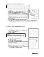
ADJUSTING THE SPEED CONTROLLER AND AIR PRESSURE   

8888----1 Adjusting the speed controller

1 Adjusting the speed controller

1 Adjusting the speed controller

1 Adjusting the speed controller    

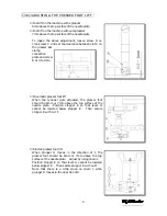
Speed controller F controls the speed when the thread 
trimming knife holder projects. 
Speed controller G controls the speed when the thread 
trimming knife holder retracts. 
If the speed is too fast, the knife holder will be greatly 
shocked.    This will cause trouble such as a thread is 
trimmed before it is caught in the knives or it is not 
clamped correctly by the thread clamp. 
If screw F is too loosened, the holder will protrude too 
fast and then the position of the movable knife will 
become unstable, causing cutting error. 
If screw G is too loosened, the holder will retract too 
fast and then a looper thread may not be held properly. 


8888----2 Air pressure

2 Air pressure

2 Air pressure

2 Air pressure


Set the regulator at 4~5kg/cm2. 
An air pressure of more than 5.0kg will cause trouble.


9

ADJUSTING THE NEEDLE THREAD WIPER   


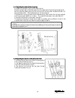
1.  Tighten screw E to position lever B horizontally. 

There should be a 0 to 0.3mm clearance between 
bracket C and stopper ring D. 

2.  Secure shaft F with screw G. 

There should be 1mm clearance between lever B 
and secure shaft F. 

3.  Position thread wiper K with screw H. 

The distance between the left end of the thread 
wiper and the center of the needle bar should be 
approximately 19mm when the thread wiper is all 
the way to the left and clearance between the 
needle center and point P of the thread wiper 
should be approximately 1mm. 

4.  The distance between the left needle and thread 

wiper K should approximately 0.5mm with screw A. 

5.  Position thread wiper K parallel with flat spring M 

with screw L. 


Summary of Contents for WX8803/UTC

Page 1: ...CTION INSTRUCTION WX LX UTC MANUAL Industrial Industrial Industrial Industrial Sewing Sewing Sewing Sewing Machines Machines Machines Machines First published August 1997 Fourth edition August 2000 No...

Page 2: ...ial s WX UTC Series Read and study this instruction manual carefully before beginning any of the procedures and save it for later use This instruction manual describes adjustments and maintenance proc...

Page 3: ...DJUSTING THE THREAD RELEASER 6 1 Thread releaser block 6 6 2 Thread releaser connection plate 6 6 3 Thread releaser lever 6 6 4 Looper thread take up 7 6 5 Thread releaser plate 7 6 6 Thread releaser...

Page 4: ...aced at position A for the next sewing operation after the threads are cut 2 INSTALLING THE POSITION DETECTOR Install position detector A and tighten screw B temporarily Fit positioner bar C onto the...

Page 5: ...en the plunger of the air cylinder protrudes 4 ADJUSTING THE THREAD TRIMMER SOLENOID 4 4 4 4 1 Solenoid stroke 1 Solenoid stroke 1 Solenoid stroke 1 Solenoid stroke The stroke of the solenoid should b...

Page 6: ...e that the looper thread clamp spring is simultaneously loosened 5 5 5 5 2 Adjusting the looper thread clamp spring 2 Adjusting the looper thread clamp spring 2 Adjusting the looper thread clamp sprin...

Page 7: ...me right end or left end of its travel The left side is a standard position for the mark N of guide lever ring R Adjustment is made by loosening the screw B of connecting lever E and moving guide bar...

Page 8: ...ead etween the movable knife needle thread and looper thread After all the adjustments are made check the following before threading to start the machine Movable knife A should enter needle thread loo...

Page 9: ...leaser connection plate 2 Thread releaser connection plate 2 Thread releaser connection plate 2 Thread releaser connection plate Fit thread releaser connection plate A onto guide screw E with a cleara...

Page 10: ...dition the length of spring H should be approximately 4mm 6 6 6 6 6 Thread releaser hook 6 Thread releaser hook 6 Thread releaser hook 6 Thread releaser hook The needle thread should not be shown long...

Page 11: ...ill retract too fast and then a looper thread may not be held properly 8 8 8 8 2 Air pressure 2 Air pressure 2 Air pressure 2 Air pressure Set the regulator at 4 5kg cm2 An air pressure of more than 5...

Page 12: ...r foot lift When the cylinder gets actuated the presser foot should be 6mm or 7mm above the top surface of the needle plate Position stopper E so that lever G cannot be lowered below stopper E Then se...

Page 13: ...by referring to 11 6 11 11 11 11 2 Adjusting the top cover thread clamp spring 2 Adjusting the top cover thread clamp spring 2 Adjusting the top cover thread clamp spring 2 Adjusting the top cover th...

Page 14: ...clearance of approximately 1mm between hook point D of movable knife C and the top cover thread Adjustment is made by loosening screws J on movable knife mounting base I 11 11 11 11 6 Adjusting the h...

Page 15: ...the pressure move up bracket D To decrease the pressure move down bracket D The pressure of spring F should be as light as possible yet be sufficient to return the movable knife home correctly when t...

Page 16: ...EUMATIC DEVICES Connect air lines and cords by referring to the illustration below and the parts list 13 WIRING AND PIPING FOR ELECTRIC DEVICES Connect air lines and cords by referring to the illustra...

Reviews: