16
Service and Repair Manual
Model 900/950/990
1.
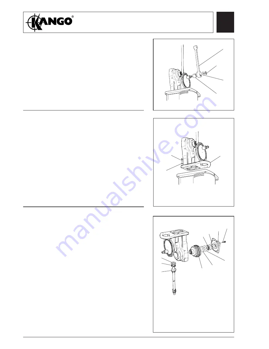
Remove the retainer circlip (307,
207, 407, 507
)
and crank pin washer (308,
208, 408, 508
).
Remove the connecting rod (305,
205, 405, 505
).
2.
Press the big end bearing (309,
209, 409, 509
)
from the connecting rod.
Removing the
connecting
rod (All
models, 950
shown)
309
209
409
509
307
207
407
507
305
205
405
505
308
208
408
508
Dismantling
the gear
carrier
assembly
(Model 950
only)
334
336
337
338
335
339
343
344
345
Removing the
gear carrier
assembly. (All
models, Model
950 shown)
1.
Hold gear carrier in vice by base. Remove the
four screws (339), and remove the clutch shaft
bearing cap (338).
2.
Using a suitable mandril, press out the clutch
shaft tail bearing (337) from the bearing cap.
3.
Remove the two thrust washers (335) and the
thrust bearing (336) and shim (334) from the
clutch shaft. Pull the clutch assembly from the
gear carrier.
4.
Remove the drive shaft (345) from the gear
carrier. Remove the drive shaft thrust race (343)
and drive shaft thrust bearing (344) from the
drive shaft.
1.
Remove six screws (320,
220, 420, 520
) and six
spring washers (319,
219, 419, 519
) securing the
gear carrier assembly to the motor casing.
2.
Remove the gear carrier assembly (318,
218, 418,
518
).
CLUTCH
ASSEMBLY
318
218
418
518
320
220
420
520
319
219
419
519
Fig. 10
Fig. 11
Fig. 12
Summary of Contents for 900
Page 1: ......


