background image

5. Avoid accidental start-up

• 

Install a main breaker switch (jack) for the winch on the positive po-

wer lead (if in doubt when choosing this switch, contact your supplier)

• 

Always disconnect the power supply when you are not using the 

winch

• 

Switch off the wireless control unit with the button on the relay box 

(if present) and switch off the wireless remote control itself with the 

button/s placed on the remote control.

6. Maintain the technical condition of the winch

• 

Before starting the work, check the condition of the winch – any da-

mage should be repaired as soon as possible by an authorized service 

centre; replace worn parts on a regular basis

• 

Use genuine spare parts only.

• 

Make sure that the rope is properly wound around the drum

• 

Keep the rope under a small load during winding; the rope 

must be wound around the drum under a minimum 5% load of the 

rated pulling force of the winch

• 

Wind the rope at right angles to the axis of the drum; in case of 

winding it at a different angle, make sure the rope 

is not wound on the drum in one place only – it may 

damage the winch or result in bodily injury or even 

death

• 

Do not let the rope move freely in the palm of your 

hand, even if you are wearing gloves – always use the 

special strap attached to the hook. Wind the rope 

according to the markings on the winch. 

Using other devices or accessories than 

those recommended herein may result in 

personal injury.


Rules of safe winch handling

Failure to follow these rules may cause an accident, resulting 

in personal injury or property damage. Familiarize yourself 

with all the rules in detail.

Small irregularities in rope winding will not cause a problem unless the 

rope starts to accumulate on one side of the drum. If this happens, unwind 

the rope a little and unload the winch, then move the hooking point of the 

rope closer to the longitudinal axis of the vehicle on which the winch is 

mounted. After finishing work, you should always rewind the rope evenly – 

this will increase its longevity as well as comfort and safety of work. 

• 

Keep the both the wired and wireless remote controls in a safe place. 

Inspect these before use

• 

Connect the remote control before turning on the clutch.

• 

NEVER move the clutch lever when the motor is turning.

• 

NEVER move the clutch lever under load.

• 

NEVER attach the hook directly around the rope, e.g. after wrapping 

the rope around a tree, as this will damage the rope. Always use an 

extra chain or strap/belt and a shackle.

• 

Watch the winch during its operation, but remember 

to keep a safe distance. Stop the winch every few 

meters to make sure that the rope is winding properly 

and evenly. Do not use the winch if you do not see the 

load being pulled or the anchor point or the rope.

• 

Do not attach additional hook holders to the winch mounting plate. 

The hook holders must be attached directly to the chassis frame. 


• 

Always use a pulley block when exceeding 

two-thirds of the maximum pulling force 

of the winch. This shall significantly incre-

ase its lifespan. The pulley block may also 

facilitate even winding of the rope on the winch drum.

• 

Make sure you use certified shackles, pulley blocks, chains and 

straps/belts only. The ultimate breaking force must match the winch 

pulling force. If in doubt, contact your supplier).

• 

NEVER unwind the entire rope. At least five wraps must 

ALWAYS remain on the drum, as otherwise the rope may 

be detached from the drum and cause an accident. 

You can replace the steel rope with a 

synthetic one, but it MUST have adequate strength that 

matches the strength of the winch. Pay attention to the 

secure and correct fastening of the rope to the drum 

and the quality of the rope. For advice on choosing a 

suitable rope, contact your supplier.

• 

The maximum pulling power of the winch shall be achieved only with 

the first layer of the rope wound on the drum. To pull heavy loads, 

unwrap as much rope from the drum as possible and/or use a pulley 

block.  

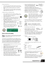
Final layers = minimum pulling force (~50-60%)*

Middle layers = average pulling force (70-80%)*

First two layers = maximum pulling force (90-100%)*

*approximate values have been provided

• 

Hang a heavy blanket or a specially desi-

gned plastic sheet on the rope (at around 

half of its length) to limit the strength 

with which the rope shall bounce off should it break.

• 

Wind the rope on the drum tightly, coil to coil, so that the upper winds 

of the rope do not cut into the lower layers. Should it happen, try to 

release the rope by pressing the winding on and unwinding buttons 

for short periods. NEVER release the rope under load by hand. 

• 

The rope:

- make sure it is properly fixed to the drum 

- Do not use a rope that is frayed, kinked and/or if pieces of wire 

protrude from it


a) twisted rope 

b) kinked rope 

c) rope repeatedly kinked and loaded / a frayed rope 


- do not use the winch rope as a tow rope (do not tow using a winch) 

– do not replace the original rope with a rope of lower 

strength (before exchanging the rope, contact your 

supplier)

- do not use the winch rope to fasten a cargo

- the lifetime of the rope depends primarily on the way it is used. Wind 

the rope on the drum under a load of at least 5% of the pulling power, 

otherwise the top layers may cut into the lower layers, which may 

damage and permanently wedge the rope together. 

3

kangaroowinch.eu

Summary of Contents for 12000PS

Page 1: ...Instrukcja obsługi wyciągarek elektrycznych 2000 6000 12000PS 12000XT HD 20000 ...

Page 2: ...ą postawę ciała uważaj by nie wpaść na lub pod linę 3 Dbaj o kabel od pilota sterującego NIGDY nie przenoś ani nie przesuwaj wyciągarki za pomocą kabla Nie szarp kablem w celu wyjęcia wtyczki pilota z gniazda Trzymaj kabel z daleka od wysokiej temperatury oleju i ostrych krawędzi 4 Nie przeciążaj wyciągarki Jeżeli silnik nagrzeje się do takiego stopnia że nie da się go dotknąć natychmiast przerwij...

Page 3: ...ekli Obserwuj wyciągarkę w czasie pracy ale pamiętaj o bezpiecznej odległości Zatrzymuj pracę co kilka metrów by upewnić się że lina nawija się prawidłowo i równomiernie Nie używaj wycią garki jeśli nie widzisz ciągniętego ładunku punktu zaczepienia lub liny Nie zaczepiaj dodatkowych uchwytów na hak do płyty montażowej wyciągarki Uchwyty muszą być mocowane bezpośrednio do ramy podwozia Powyżej 2 3...

Page 4: ...rczonych w komplecie z wyciągarką oraz wszystkich elementów płyty montażowej Dopiero mając pewność że mechanicznie jest w pełni zamocowana przejdź do podłączania elektryki 1 Mocowanie wyciągarki Wyciągarkę należy zamocować przy pomocy dostarczonych śrub na płaskiej powierzchni o wytrzymałości odpowiedniej do maksymalnej siły uciągu wyciągarki W zależności od modelu w zestawie może być 2 4 lub 8 śr...

Page 5: ...iec długiego CZERWONEGO kabla do bieguna akumulatora Zawsze podłączaj czarny przewód tylko bezpośrednio do akumu latora Nigdy nie używaj innej masy znajdującej się na pojeździe Na czerwonym przewodzie należy zastosować wyłącznik bezpie czeństwa oraz bezpiecznik Przy podłączaniu bezpiecznika upewnij się że jest odpowiednio zainstalowany posiada on oznaczenie wskazujące które przyłącze należy podpią...

Page 6: ...miń go lub zakup osobno u dostawcy 6000 BATERIA Żółty Niebieski Zielony przewód do gniazda pilota Czarny przewód do akumulatora Czarny przewód do gniazda pilota Czerwony przewód do gniazda pilota Czerwony przewód do akumulatora BATERIA Czarny kabel Czarny kabel Czarny kabel Czarny kabel Czerwony kabel Czerwony kabel Czerwony kabel Żółty kabel Żółty kabel Antena REMOTE Biały kabel Biały kabel Niebi...

Page 7: ...7 20000 BATERIA kangaroowinch eu ...

Page 8: ...y zaczep o szeklę pilnuj aby zapadka haka była zamknięta i nie pod trzymywała obciążenia nie osadzaj obciążenia na rogu haka lub zapadce Obciążenie musi być osadzone na środku gardzieli haka NIGDY nie używaj odkształconego haka 4 Sprawdź poprawność podłączenia kabli zasilających przed pierwszym użyciem i po każdym serwisie demontażu 5 Włóż wtyczkę pilota do gniazda na skrzynce z przekaźnikami Zale...

Page 9: ...yłączaj pilota bezprze wodowego nadajnik oraz centralkę sterowania przycisk na skrzynce z przekaźnikami jeśli występuje NIE pozwól aby dzieci bawiły się żadnym z pilotów sterujących pracą wyciągarki Prawie każda wyciągarka KANGAROOWINCH jest standardowo wyposażona w sterowanie radiowe Jeśli Twoje sterowanie uległo uszkodzeniu lub stracił się nadajnik pilot skontaktuj się ze sprzedawcą Przed wyciąg...

Page 10: ...łączeń elektrycznych oczyść je i dociągnij śruby aby zapewnić najlepszy przepływ prądu Żadne inne czynności konserwacyjne nie są wymagane poza oczysz czaniem wyciągarki z błota używaj szczotki i bieżącej wody nie myjki ciśnieniowej W razie jakichkolwiek kłopotów lub niejasności prosimy o kontakt ze sprzedawcą Wyciągarkę używaną ekstremalnie należy konserwować częściej Może być konieczne przeprowad...

Page 11: ...NETTO STAL SYNTETYK 13 2 kg 10 1 kg 1 kg płyta montażowa WYMIARY 381 x 133 x 196 5 mm OSIĄGI Obciążenie kg 0 680 1361 2041 2720 lbs 0 1500 3000 4500 6000 Prędkość zwijania liny 12V m min 5 8 3 4 2 65 1 8 1 2 FT min 19 03 11 15 8 69 5 91 3 94 Pobór prądu 12V Amper 29 93 136 188 256 Prędkość zwijania liny 24V m min FT min Pobór prądu 24V Amper warstwa 1 2 3 4 5 Uciąg na poszczególnych warstwach kg 2...

Page 12: ...3063 0 lbs 12000 9522 7892 6738 0 Skumulowana długość liny na bębnie m 5 4 11 2 18 8 26 8 0 ft 16 25 36 7 61 5 88 0 20000 UCIĄG 9080 KG 20000 LBS SILNIK 6 5KM 4 78kW szeregowy PRZEKAŹNIKI Hermetyczny solenoid STEROWANIE Na przewodzie 3 45m PRZEKŁADNIA 3 stopniowa planetarna PRZEŁOŻENIE 358 4 1 HAMULEC Cierny w bębnie LINA STAL SYNTETYK 13mm x 22m PROWADNICA LINY 4 rolkowa KABLE ZASILAJĄCE 170cm 35...

Page 13: ...ny pin 3x11 1 9 Wałek wieloklinowy 1 10 Sprężyna 1 11 Bęben 1 12 Śruba liny M5 1 Nr Nazwa Ilość 13 Łożysko bębna 1 14 Nakrętka z kołnierzem M5 2 15 Dociskacz liny 1 16 Podstawa wyciągarki 1 17 Dźwignia sprzęgła 1 18 Śruba stożkowa M5x10 2 19 Śruba imbusowa M6x16 2 20 Lina stalowa 1 21 Prowadnica rolkowa 1 22 Pilot sterowania 1 23 Hak widełkowy z zabezpieczeniem 1 24 Pasek na hak 1 RYSUNKI TECHNICZ...

Page 14: ... Podstawa manetki sprzęgła 1 19 Piny manetki sprzęgła 3 20 Osłona podstawy manetki sprzęgła 1 Nr Nazwa Ilość 21 Śruba M4X10 3 22 Śruba z podkładką M4X8 1 23 Manetka sprzęgła 1 24 Sprężyna 6 25 Pręt ściągający dolny 1 26 Bęben 1 27 Łożysko ślizgowe 2 28 Simering 2 29 Zespół hamulca 1 30 Lina stalowa syntetyczna 1 31 Hak widełdowy z zabezpie czeniem 1 32 Pasek na hak 1 Nr Nazwa Ilość 35 Śruba M8X20 ...

Page 15: ...ni sprzęgła 1 27 Śruba imbusowa M4x16 1 28 Sprężyna sprzęgła 1 29 Swożeń sprzęgła 1 Nr Nazwa Ilość 30 O ring 1 31 Śruba M6x10 1 32 Śruba M5x16 8 33 Podkładka sprężynująca 8 34 Obudowa przekładni 1 35 Łożysko 1 36 Zębatka 1 stopnia przekładni 1 37 1 stopień przekładni 1 38 2 stopień przekładni 1 39 Pierścień sprzęgła 1 40 kabel zasilający 2 41 Pilot radiowy 1 42 Pasek na hak 1 43 Podkładka sprężynu...

Page 16: ...awa skrzynki z przekaź nikami 1 23 Śruby skrzynki z przekaźnikami 4 24 Śruby skrzynki z przekaźnikami 2 25 Kabel zasilający 1 26 Odbiornik sterowania radiowego 1 27 Zestaw montażowy skrzynki nad bębnem 2 Nr Nazwa Ilść 28 Zestaw montażowy skrzynki nad bębnem 2 29 Pin 4X8 4 30 Stopa mocująca przekładni 1 31 Bieżnia przekładni planetarnej 1 35 Uszczelka 1 36 Zespół dźwigni sprzęgła 1 37 Zespół dźwign...

Page 17: ...azwa Ilość 14 Śruba dźwigni sprzęgła 1 15 Uszczelka 1 16 Osłona sworznia sprzęgła 1 17 Dźwignia sprzęgła 1 18 Obudowa przekładni 1 19 Śruba imbusowa M8X25 4 20 Podkładka sprężynująca 4 21 Stopa mocująca przekładni 1 22 Śruba imbusowa M5X16 10 23 Podkładka sprężynująca 10 24 Łożysko ślizgowe 2 25 Simering 2 26 Pręt ściągający 2 Nr Nazwa Ilość 27 Bęben 1 28 Wałek napędowy 1 29 Śruba imbusowa M4X16 6...

Page 18: ...NOTATKI 18 kangaroowinch eu ...

Page 19: ...niu z kupującym 9 Okres gwarancji przedłużony zostaje o okres trwania obsługi gwarancyjnej Nie dotyczy to przypadku gdy stwierdzone zostanie iż naprawa nie jest naprawą gwarancyjną 10 Gwarancja nie obejmuje uszkodzeń wynikających z używania niewłaściwego lub niezgodnego z instrukcją ob sługi i użytkowania a także niewłaściwego przechowywania oraz konserwacji i smarowania wyciągarki 11 Gwarancja ni...

Page 20: ...POLSKA INFO KANGAROOWINCH EU WWW KANGAROOWINCH EU TEL 48 12 266 27 54 FAX 48 12 269 63 61 ...

Page 21: ...Electric winch instructions manual 2000 6000 12000PS 12000XT HD 20000 ...

Page 22: ... to such a temperature that it cannot be to uched stop working immediately and allow it to cool down Stop working immediately when the motor stops because it is unable to pull a load that is too heavy use a pulley block and wait until the motor cools down Do NOT exceed the specified maximum pulling force of the winch avoid jerking Prior to working with the winch please become acquainted with the s...

Page 23: ...distance Stop the winch every few meters to make sure that the rope is winding properly and evenly Do not use the winch if you do not see the load being pulled or the anchor point or the rope Do not attach additional hook holders to the winch mounting plate The hook holders must be attached directly to the chassis frame Always use a pulley block when exceeding two thirds of the maximum pulling for...

Page 24: ...pulling force Depending on the model there may be two four or eight screws in the set All bolts must be placed in the same plane in holes with appropriate spacing to avoid dama ge to the winch Make sure that the installation method does not interfere with operation of the sensor systems i e those related to activation of the airbags or other systems in the vehicle e g radar The assembly of the win...

Page 25: ...safety circuit breaker and a fuse When connecting the fuse make sure it is properly installed There is a marking to indicate which connector should be connected to the wire to the battery and which to the wire to the motor When routing the wires make sure that they are not placed next to movable parts that may break the insulation or wire Never place wires on sharp edges that may cut the insulatio...

Page 26: ...to the remote control socket Red wire to the remote control socket Red wire to the battery 12000PS BATTERY Black wire Black wire Black wire Black wire Red wire Red wire Red wire Yellow wire Yellow wire Antenna REMOTE White wire White wire Blue wire Red wire 12000XT HD battery Connection A thin black wire with white jacket Connection A long black power supply wire to the battery Connection B short ...

Page 27: ...20000 BATTERY kangaroowinch eu 7 ...

Page 28: ...ply the load on the tip of the hook or the latch The load must be placed in the middle of the hook throat NEVER use a deformed hook 4 Check the correctness of connecting the power wires before the first use and after each service or disassembly 5 Insert the remote control plug into the socket on the relay box We recom mend controlling the winch from the inside of the vehicle for greater safety in ...

Page 29: ...control transmitter and the control unit button on the relay box if present DO NOT allow children to play with any of the remote controls for the winch Almost every KANGAROOWINCH winch is equipped with a radio control system as standard If your remote control has been damaged or the transmitter has been lost contact your supplier Before you pull the vehicle out ALWAYS put the vehicle s gearbox to ...

Page 30: ...lly check whether the winch fastening bolts are tight Condition of electrical connections clean them and tighten the screws to ensure the best current flow No other maintenance is required except for cleaning the winch from the mud use a brush and running water but not a pressure washer In case of any problems please contact your supplier Should the winch be used extensively more frequent maintena...

Page 31: ...HT STEEL SYNTHETICS 13 2 kg 10 1 kg 1 kg mounting plate DIMENSIONS 381 x 133 x 196 5 mm PERFORMANCE DATA Load kg 0 680 1361 2041 2720 lbs 0 1500 3000 4500 6000 Rope winding speed 12V m min 5 8 3 4 2 65 1 8 1 2 FT min 19 03 11 15 8 69 5 91 3 94 Operation amperage 12V Ampere 29 93 136 188 256 Rope winding speed 24V m min FT min Operation amperage 24V Ampere layer 1 2 3 4 5 Pulling capacity for respe...

Page 32: ...63 0 lbs 12000 9522 7892 6738 0 The cumulative rope length on the drum m 5 4 11 2 18 8 26 8 0 ft 16 25 36 7 61 5 88 0 20000 PULLING CAPACITY 9080 KG 20000 LBS MOTOR 6 5KM 4 78kW szeregowy RELAYS Hermetyczny solenoid CONTROL SYSTEM Na przewodzie 3 45m TRANSMISSION 3 stopniowa planetarna TRANSMISSION RATIO 358 4 1 BRAKE Cierny w bębnie ROPE STEEL SYNTHETIC 13mm x 22m CABLE GUIDE 4 rolkowa POWER CORD...

Page 33: ...9 Spline shaft 1 10 Spring 1 11 Drum 1 12 M5 rope bolt 1 No Name Quantity 13 Drum bearing 1 14 Flanged M5 nut 2 15 Rope clamp 1 16 Winch base 1 17 Clutch lever 1 18 M5x10 conical screw 2 19 Allen screw M6x16 2 20 Steel rope 1 21 Roller guide 1 22 The remote control 1 23 Fork head hook with safety catch 1 24 Hook up strap 1 TECHNICAL DRAWINGS AND DIAGRAMS 2000 REPLACEMENT PARTS LIST 2000 kangaroowi...

Page 34: ...h lever 1 19 Pins of the clutch lever 3 20 Cover for the clutch lever base 1 No Name Quantity 21 M4X10 screw 3 22 Screw with washer M4X8 1 23 Clutch lever 1 24 Spring 6 25 Bottom tie rod 1 26 Drum 1 27 Plain bearing 2 28 Oil seal ring 2 29 Brake assembly 1 30 STEEL SYNTHETIC rope 1 31 Fork head hook with safety catch 1 32 Hook up strap 1 No Name Quantity 35 M8X20 screw 2 36 Rope guide roller slidi...

Page 35: ... the clutch lever 1 27 Allen screw M4x16 1 28 Clutch spring 1 29 Clutch pin 1 No Name Quantity 30 O ring 1 31 M6x10 screw 1 32 M5x16 screw 8 33 Spring washer 8 34 Gear housing 1 35 Bearing 1 36 FirstFirst stage sun gear 1 37 FirstFirst stage planetary gear 1 38 SecondSecond stage plane tary gear 1 39 Clutch ring 1 40 Power supply cord 2 41 Wireless remote control 1 42 Hook up strap 1 43 Spring was...

Page 36: ... relays 4 24 Screws for the box with relays 2 25 Power cord 1 26 Wireless remote control receiver 1 27 Assembly kit for the box over the drum 2 No Name Quantity 28 Assembly kit for the box over the drum 2 29 Pin 4X8 4 30 Gear mounting flange 1 31 Ring gear 1 35 Gasket 1 36 Clutch lever assembly 1 37 Clutch lever assembly 1 38 Clutch lever assembly 1 40 Gear housing 1 43 Wireless and wired remote c...

Page 37: ...y 13 Fourth stage planetary gear 1 14 Clutch lever screw 1 15 Gasket 1 16 Clutch pin cover 1 17 Clutch lever 1 18 Gear housing 1 19 Allen screw M8X25 4 20 Spring washer 4 21 Gear mounting flange 1 22 Allen screw M5X16 10 23 Spring washer 10 24 Plain bearing 2 No Name Quantity 25 Oil seal ring 2 26 Tie rod 2 27 Drum 1 28 Drive shaft 1 29 Allen screw M4X16 6 30 Spring washer 6 31 Brake assembly 1 32...

Page 38: ...NOTES 18 kangaroowinch eu ...

Page 39: ...milar parameters The Guarantor shall exchange it in consultation with the purchaser 9 The warranty period is extended by the duration of warranty service This does not apply should the repair turn out not to be covered with the warranty 10 The warranty does not cover damage resulting from improper use or use inconsistent with the user manual or improper storage maintenance and lubrication of the w...

Page 40: ...POLSKA INFO KANGAROOWINCH EU WWW KANGAROOWINCH EU TEL 48 12 266 27 54 FAX 48 12 269 63 61 ...

Page 41: ...Elektrische Seilwinde Bedienungsanleitung 2000 6000 12000PS 12000XT HD 20000 ...

Page 42: ...n um den Stecker der Fernbedienung aus der Steckdose zu ziehen Kabel vor hohen Temperaturen Öl und scharfen Kanten schützen 4 Seilwinde nicht übermäßig belasten Wenn der Motor so heiß ist dass man ihn nicht berühren kann sofort den Betrieb einstellen und warten bis er abkühlt Betrieb sofort unterbrechen wenn der Motor stehen bleibt weil er nicht in der Lage ist eine so große Last zu ziehen Flasche...

Page 43: ...n Kupplungshebel NIEMALS unter Last schalten Haken NIEMALS direkt am Seil befestigen z B nach dem man das Seil um einen Baum gewickelt hat da auf diese Weise das Seil beschädigt wird Immer eine zusätzliche Kette oder ein Band einen Gurt und einen Schäkel verwenden Die Seilwinde während des Betriebs beobachten dabei den Sicherhe itsabstand einhalten Den Betrieb alle paar Meter unterbrechen um siche...

Page 44: ...te man versuchen den Hebel mit einer Hand zu drehen und mit der anderen die sich auf der Fernbedienung befindenden Tasten Aufwickeln und Abwickeln abwechselnd zu drücken Nach einer gewissen Zeit werden die Getrie bezähne einrasten Das oben beschriebene Verfahren DARF MAN UNTER KEINEN UMSTÄNDEN ausführen wenn die Seilwinde belastet ist Montage der Seilwinde Zuerst die Seilwinde mit Hilfe aller mit ...

Page 45: ...des SCHWARZEN Kabels an den Minuspol der Batterie anschließen Schritt 2 Das freie Ende des ROTEN Kabels an den Pluspol der Batterie anschließen Das schwarze Kabel immer direkt an die Batterie an schließen Niemals einen anderen sich am Fahrzeug befin denden Masseanschluss verwenden Die rote Leitung ist mit einem Sicherheitsschalter und einer Sicherung zu versehen Nach dem Anschluss der Sicherung so...

Page 46: ...r Fernbedienung Rote Leitung zur Steckdose der Fernbedienung Rote Leitung zur Batterie 12000PS BATTERIE Schwarzes Kabel Schwarzes Kabel Schwarzes Kabel Rotes Kabel Rotes Kabel Rotes Kabel Gelbes Kabel Gelbes Kabel Antenne REMOTE Weißes Kabel Blaues Kabel Rotes Kabel 12000XT HD Batt erie Anschluss A dünnes schwarzes Kabel mit weißer Ummantelung Anschluss A langes schwarzes Speisekabel zur Batterie ...

Page 47: ...9 20000 BATTERIE 7 kangaroowinch eu ...

Page 48: ...n Darauf achten dass die Sperrklinke am Haken geschlossen ist und die Last nicht stützt Die Last nicht an der Hakenspitze oder an der Sperrklinke anschlagen Die Last muss sich in der Mitte des Hakenbogens befinden NIEMALS einen verformten Haken benutzen 4 Die korrekte Verbindung der Speisekabel prüfen vor der Erstinbetriebna hme und nach jeder Wartung Demontage 5 Stecker der Fernbedienung in die S...

Page 49: ... dem Relaiskasten sofern vorhanden immer ausschalten Ander nfalls kann die Batterie in der Fernbedienung entladen und die Seilwinde aus Versehen in Betrieb gesetzt werden Die Fernbedienung IMMER zwischen den einzelnen Einsätzen der Seilwinde ausschalten auch wenn die Pause kurz ist Bevor man die kabellose Fernbedienung verwendet sollte man IMMER den Stecker der kabelgebundenen Fernbedienung heraus...

Page 50: ...timalen Stromfluss zu gewährleisten Weitere Wartungsarbeiten sind nicht erforderlich Ausnahme Reinigung der Seilwinde vom Schlamm Bürste und fließendes Wasser verwenden es dürfen keine Hochdruckreiniger eingesetzt werden Bei Problemen oder Zweifeln setzen Sie sich bitte mit dem Verkäufer in Verbindung Seilwinden die unter sehr schwierigen Einsatzbedingungen verwendet werden sollten öfter gewartet ...

Page 51: ... kg Montageplatte ABMESSUNGEN 381 x 133 x 196 5 mm LEISTUNGSWERTE Last kg 0 680 1361 2041 2720 lbs 0 1500 3000 4500 6000 Aufwickelgeschwindigkeit des Seiles 12V m min 5 8 3 4 2 65 1 8 1 2 FT min 19 03 11 15 8 69 5 91 3 94 Stromentnahme 12V Ampere 29 93 136 188 256 Aufwickelgeschwindigkeit des Seiles 24V m min FT min Stromaufnahme 24V Ampere Lage 1 2 3 4 5 Zugkraft für einzelne Lagen kg 2720 2421 2...

Page 52: ...12000 9522 7892 6738 0 Gesamtlänge des Seiles auf der Trommel m 5 4 11 2 18 8 26 8 0 ft 16 25 36 7 61 5 88 0 20000 ZUGKRAFT 9080 KG 20000 LBS MOTOR 6 5KM 4 78kW Reihenschaltung RELAIS Hermetische Zylinderspule STEUERUNG Kabelgebunden 3 45m GETRIEBE Planetengetriebe 3 stufig ÜBERSETZUNG 358 4 1 BREMSE Reibungsbremse in der Trommel SEIL STAHL SYNTHETISCH 13mm x 22m SEILFÜHRUNG mit 4 Rollen SPEISEKAB...

Page 53: ... 3x11 1 9 Keilwelle 1 10 Feder 1 11 Trommel 1 12 Schrauben M5 für das Seil 1 Nr Bezeichnung Anzahl 13 Trommellager 1 14 Mutter mit Flansch M5 2 15 Seilniederhalter 1 16 Aufnahme der Seilwinde 1 17 Kupplungshebel 1 18 Konusschraube M5x10 2 19 Inbusschraube M6x16 2 20 Stahlseil 1 21 Rollenführung 1 22 Fernbedienung der Steuerung 1 23 Gabelhaken mit Sicherung 1 24 Hakengurt 1 TECHNISCHE ZEICHNUNGEN U...

Page 54: ...s Kupplungshe bels 1 19 Stifte des Kupplungshebels 3 20 Aufnahmedeckel des Kupplun gshebels 1 Nr Bezeichnung Anzahl 21 Schraube M4X10 3 22 Schraube mit Unterlegscheibe M4X8 1 23 Kupplungshebel 1 24 Feder 6 25 Unterer Abziehstab 1 26 Trommel 1 27 Gleitlager 2 28 Simmering 2 29 Bremsanlage 1 30 Stahlseil synthetisches Seil 1 31 Gabelhaken mit Sicherung 1 Nr Bezeichnung Anzahl 32 Hakengurt 1 35 Schra...

Page 55: ...usschraube M4x16 1 28 Kupplungsfeder 1 Nr Bezeichnung Anzahl 29 Kupplungsbolzen 1 30 O Ring 1 31 Schraube M6x10 1 32 Schraube M5x16 8 33 Federring 8 34 Getriebegehäuse 1 35 Lager 1 36 Zahnscheibe der 1 Getrie bestufe 1 37 1 Stufe des Getriebes 1 38 2 Stufe des Getriebes 1 39 Kupplungsring 1 40 Speisekabel 2 41 Fernbedienung für Funksteu erung 1 Nr Bezeichnung Anzahl 42 Hakengurt 1 43 Federring 4 4...

Page 56: ...astens 4 24 Schrauben des Relaiskastens 2 25 Speisekabel 1 26 Empfänger der Funksteuerung 1 27 Montageset des Kastens über der Trommel 2 28 Montageset des Kastens über der Trommel 2 29 Stift 4X8 4 Nr Bezeichnung Anzahl 30 Spannfuß des Getriebes 1 31 Hohlrad des Planetengetriebes 1 35 Dichtung 1 36 Kupplungshebelset 1 37 Kupplungshebelset 1 38 Kupplungshebelset 1 40 Getriebegehäuse 1 43 Fernbedienu...

Page 57: ...lanetengetriebes 1 Nr Bezeichnung Anzahl 14 Schraube des Kupplungshebels 1 15 Dichtung 1 16 Abdeckung des Kupplungsbol zens 1 17 Kupplungshebel 1 18 Getriebegehäuse 1 19 Inbusschraube M8X25 4 20 Federring 4 21 Spannfuß des Getriebes 1 22 Inbusschraube M5x16 10 23 Federring 10 24 Gleitlager 2 25 Simmering 2 Nr Bezeichnung Anzahl 26 Abziehstab 2 27 Trommel 1 28 Antriebswelle 1 29 Inbusschraube M4X16...

Page 58: ...25 NOTIZBUCH 18 kangaroowinch eu ...

Page 59: ... im Einvernehmen mit dem Käufer durch 9 Die Garantiezeit wird um die Dauer der Garantieleistung verlängert Dies gilt nicht wenn es sich bei der Instandsetzung um keine Garantiereparatur handelt 10 Die Garantie umfasst keine Schäden die sich aus einer unsachgemäßen oder mit der Bedienungs und Gebrauchsanle itung nicht übereinstimmenden Handhabung und einer unsachgemäßen Aufbewahrung sowie Wartung u...

Page 60: ...POLSKA INFO KANGAROOWINCH EU WWW KANGAROOWINCH EU TEL 48 12 266 27 54 FAX 48 12 269 63 61 ...
Reviews: