background image

Nesis III User’s Manual

3.11

Screen Elements

Figure 24:

Illustration of the mini engine monitor.

3.11.8

Fuel Computer Monitor

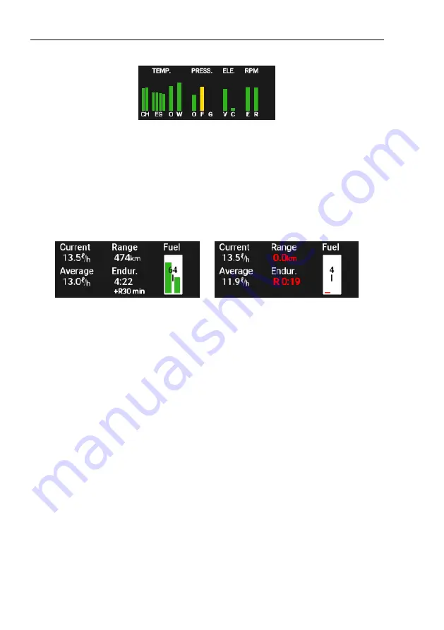
The fuel computer monitor provides the fuel related information like fuel
quantity, economy, range and endurance. Figure 25 shows an example of such
information.

(a)

Normal situation with endurance
of 4 hours and 22 minutes with a
30 min reserve.

(b)

Endurance without any reserve
and range of 0 km.

Both are

shown in red.

Figure 25:

Fuel computer displays fuel economy, fuel level, endurance and
range.

The fuel computer monitor provides the following information:

The current fuel consumption displays momentary fuel burning rate. It
is given in l/h (liter per hour) or gal/h (gallons per hour) units.

The average fuel consumption displays a value depending on the Fuel
compute mode. See also section 8.3.3 on page 89.

In the

Manual

mode the setting specified value is always shown for

the average fuel consumption.

In the

Automatic

mode, the average value from the settings is

shown while not flying (on the ground). After take-off, the average
fuel consumption is calculated from the fuel flow. The complete
flight after take-off is taken into account in this calculation.

46

©

Kanardia

2018-2022

Summary of Contents for Nesis III

Page 1: ...Nesis III User s Manual Kanardia d o o April 2022 Release for software version 3 9...

Page 2: ......

Page 3: ...http creativecommons org licenses by sa 3 0 In short the license gives you right to copy reproduce and modify this document if you cite Kanardia d o o as the author of the original work you distribute...

Page 4: ...document Date Description Sep 2018 Complete manual rework to match software version 3 3 Jan 2019 SW 3 4 GNSS Constellation window added CTR is shown filled UL Power MWFly engine Trig radio Eagle Flar...

Page 5: ...y Overview 19 3 1 1 Touch Screen 20 3 2 Turning ON OFF 21 3 3 Start up Sequence 21 3 4 Status Bar 21 3 4 1 GDL90 Devices 24 3 5 Screens 24 3 6 Classic Screen 25 3 7 Navigation Screen 27 3 7 1 Main Ele...

Page 6: ...Fuel 47 3 11 10Direction Indicator 47 3 11 11Special Markings on Engine Parameters 48 4 Flight Time Activities 49 4 1 Main Menu 49 4 2 QNH 50 4 2 1 QFE Setting 50 4 2 2 Initial QNH Setting 51 4 3 Rad...

Page 7: ...Traffic on the Moving Map 66 5 3 Warning 67 5 4 Settings 69 5 4 1 Info 70 5 4 2 General Settings 71 5 4 3 ADS B Settings 72 5 4 4 Range Settings 73 5 5 Errors 73 5 5 1 New traffic messages 74 6 Engine...

Page 8: ...ne Shut Down 94 8 3 9 Glide 95 8 4 Pilots 96 8 5 Alarms 97 8 5 1 Editing an Alarm 98 8 6 Brightness 99 8 7 Audio 99 8 8 Compass 100 8 9 ADSB Flarm 100 8 10 Waypoints 100 8 10 1 New Waypoint 100 8 10 2...

Page 9: ...1 Database Update 114 11 1 Updating with USB Stick 115 11 1 1 Downloading Updates 115 11 1 2 Copying Update File to the USB Stick 115 11 1 3 Performing the Update 116 11 2 Update with WiFi 116 12 Auto...

Page 10: ...4 User Charts 129 13 3 5 Installing a Raster Map 129 13 4 Installing Approach Maps 130 14 Third Party Software 130 14 1 The Qt Library 131 14 1 1 Modules and Linking 131 14 1 2 Source Code and Toolcha...

Page 11: ...nual A few icons appear on the side of the manual which have special meanings This icon denotes information that needs to be taken with special attention This icon denotes background information about...

Page 12: ...bility to look out to see and avoid other aircraft The other aircraft position depicted on the screen may be wrong due to lack of proper equipment poor reception and inaccurate or old information Do n...

Page 13: ...complexity of the system the pilot must accept that pro viding self test capability for all possible system failures is not practical This means that an erroneous operation may occur without a fault...

Page 14: ...the major part of the sys tem It acts as a primary multi functional dis play Internally it hosts an embedded computer and an AD AHRS GPS module called AIRU The em bedded computer reads information fro...

Page 15: ...temperature carburetor temperature airbox gearbox temperature fuel lev els system voltage electrical current oil pressure fuel pressure hydraulics pressure pitch trim flap position and many others DA...

Page 16: ...n Two different SERU units are avail able Stronger and heavier has 6 Nm 53 in lb torque while the lighter and weaker has 3 Nm 27 in lb torque Remote autopilot panel called AMIGO brings fur ther enhanc...

Page 17: ...airspace updates and to access weather information An external carbon monoxide CO sensor can be connected directly to Nesis In the case of elevated CO concentration buildup a visual and acoustic alar...

Page 18: ...lmost immediately while Nesis primary display is still booting One or more slave round instruments can be added to the bus They can show almost any value which is available on the bus The most typical...

Page 19: ...touch screen It works just as touch on tablets and telephones do It detects single touch long single touch multi touch touch and drag swipe 2 The Selector knob detects knob rotation short push and lo...

Page 20: ...for about two seconds An associated action will be activated after two second period even if the button was not released yet Nothing happens on release 3 1 1 Touch Screen The touch screen significant...

Page 21: ...m the warning push the knob 2 select the pilot 3 select the instructor 4 select the QNH rotate until correct QNH is shown and then push the knob 5 Set the fuel level for software tanks only not shown...

Page 22: ...he top and current course on the bottom A yellow line left of the center means that you should steer left and a yellow line right of the center means you should steer left Steering indicator is pretty...

Page 23: ...s further enhanced with some augmentation system WAAS EG NOS etc Flarm Symbols These symbols appear only when some of Flarm devices is connected to the Nesis If none of the symbols is shown it means t...

Page 24: ...used it is working properly A red symbol indicates that device is in errorneous state and it should not be trusted When a connection was not established no sysmbol will apear This means that either d...

Page 25: ...switch between the screens More details about each screen are given in next sections 3 6 Classic Screen The classic flight information screen shows information which is the pilot s primary concern Th...

Page 26: ...and middle scale respectively The ball indicates the side slip Trim indicators roll pitch yaw are shown on the right bottom part of the horizon when trim position sensors are connected A touch on the...

Page 27: ...corresponds to one parameter and the color of the bar to its current status See also section 3 11 7 on page 45 Alternatively an airplane designation can be shown instead 9 The fuel computer window pro...

Page 28: ...ing remain the same A long touch on the compass rose will set the heading bug 4 The map orientation button It shows the orientation of the map red arrow points to the North A touch on the button chang...

Page 29: ...rofile window The profile is always shown in the tracking direction in the direction of the blue prediction line The window also shows current baro corrected altitude A touch on the window makes it la...

Page 30: ...ation screen in the pan mode 1 2 3 4 Figure 8 Example of OFM details very good coverage with a lot of details Where ever such details are available they are included in the Nesis Figure 8 illustrates...

Page 31: ...iver supporting GDL90 protocol US only a weather overlay is shown over the base map The transparency of the weather can be adjusted Figure 9 A weather overlay example 3 8 1 Approach Maps Nesis automat...

Page 32: ...re any installation just click and run There is a separate manual dedicated to the Approacher app which pro vides step by step instructions of the map creation process Select SUPPORT Documentation sec...

Page 33: ...ic details are tuned See section 3 8 3 Airspace Opens a new window where visibility of airspace zones can be defined See section 3 8 4 for more details Approach tranparency is used to adjust the trans...

Page 34: ...te 3 8 4 Airspace Filter Airspace zones appearance can also be tuned Airspace structure can be quite complex and it can be difficult to understand in a top down view In order to improve readability so...

Page 35: ...elow During flight all zones which top is more then speci fied distance below current flight altitude will be hidden Again this changes dynamically 3 9 Engine Screen The engine monitoring screen displ...

Page 36: ...air temperature indication Note that the engine screen does not show the status bar on the top 3 10 Modern Screen The modern screen combines big artificial horizon and other primary flight indication...

Page 37: ...ical speed scale 4 Altitude tape A height above ground level AGL and current QNH value are shown at the bottom Altitude bug is shown in orange A touch on the QNH area of the altitude tape will open QN...

Page 38: ...section voltage and current 13 Fuel computer values A touch on this toggles the values 14 Fuel tank combination Left and right tank and sum of both below 3 10 1 Modern Screen with Moving Map There are...

Page 39: ...display indicated and true airspeed Indi cated airspeed IAS is obtained from differential pressure sensor The mea sured differential pressure the difference between the total pressure and the static p...

Page 40: ...nding or take off Depending on the aircraft the white range may have additional upper speed limits which are based on flap extension step See also VFE1 and VFE2 The white range in a helicopter may be...

Page 41: ...full flap extension limit is represented by VFE2 3 11 2 Small Attitude Indicator The attitude indicator also known as artificial horizon AHRS is used to inform the pilot on the orientation of the airc...

Page 42: ...e Indicator The altitude indicator also known as altimeter is used to measure the atmo spheric pressure from a static port outside the aircraft This measurement is then converted into an altitude abov...

Page 43: ...cify green and yellow range Hence such range is optional The optional green range defines the recommended range of RPM The op tional yellow range defines the range of RPM which should not be used for...

Page 44: ...d prerotation helper lamp Prerotation lamp is used during rotor prerotation process as a part of takeoff procedure Red lamp is shown as long as rotor RPMs are has not reached the minimal safe value Th...

Page 45: ...he combination of rotor RPM and engine RPM Both scales are in percentages Like in the gyroplane case the bottom window can be configured to show the manifold pressure 3 11 7 Mini Engine Monitor The mi...

Page 46: ...durance and range The fuel computer monitor provides the following information The current fuel consumption displays momentary fuel burning rate It is given in l h liter per hour or gal h gallons per...

Page 47: ...ated during the flight The fuel level is reduced by subtracting the fuel flow integrated in time Both the initial information and the fuel flow integration may be source of significant error which can...

Page 48: ...s for low sensor condition the sensor has reached the low mea suring point Example Real CHT temperature is 5 degrees but sensor is able to measure only values above 25 degrees In this case you will se...

Page 49: ...ccessible from the main menu 4 1 Main Menu A push on the knob brings up the main menu This happens on all screens Figure 29 shows the main menu for the Classic Screen Some other screens may have less...

Page 50: ...vailable on the Map screen only It opens a window for the map layer manipulation Options Opens options screen used to tune the system settings See section 8 starting on page 84 for more details 4 2 QN...

Page 51: ...the Installation Manual for more details The frequency is set in a window as shown on Figure 31 Figure 31 Setting the standby frequency value The frequency is set in three steps First value left of d...

Page 52: ...me filter right First Step The following options are available in the first step Deactivate This option is visible only if some waypoint was previously made active It will deactivate navigation mode A...

Page 53: ...umber of listed waypoints will rapidly decrease Nesis searches both the name and the waypoint description Matching part of the name is marked in green 4 4 1 Creating a Marker The New Marker option fro...

Page 54: ...esis is connected to the Internet METAR reports are shown In addition when the METAR report is selected a new window is opened where the METAR report is interpreted in a more friendly form For an exam...

Page 55: ...e manipula tion window See Figure 35 right 4 5 1 Activating a Route With no active route a window opens like shown on Figure 35 left Routes are sorted alphabetically Route name is typically defined by...

Page 56: ...en A route consists of a takeoff and landing airfield Between these two there may be several intermediate waypoints The route creation process will be shown on an example of a route from LJCL Celje to...

Page 57: ...labeled as New in between Select the New item to add MW1 MUREG and SASAL waypoints in sequence All these are VFR waypoints so select VFR or All when asked for a waypoint type The final situation is s...

Page 58: ...een is used extensively in planning The route creation process will be shown on an example on a route from LJSK Slovenjske Konjice to LOAV Bad Vo slau This route may have the following intermediate VF...

Page 59: ...te route At the bottom is the terrain profile with the airspace zones that route is crossing Adjust the vertical flight line according to the terrain and airspace Once you are happy with the route sel...

Page 60: ...elds close to the route and display this in a list form Either an Internet access or an active FIS B link connection is required for this command Figure 39 shows an example Estimated elapsed time EET...

Page 61: ...the route into Nesis but it will not make it active 4 5 5 Deleting a Route Select a route from the list of routes and then select the Delete command The selected route will be deleted from the list T...

Page 62: ...his is a very convenient command It reverses order of items in selected route Route name is also automatically adjusted unless route was previously renamed Figure 40 shows a reversed route from the pr...

Page 63: ...culates the fuel remaining from the fuel flow information Note that such way of fuel level indication is highly speculative and may lead to very inaccurate results Never fully trust this indication Fu...

Page 64: ...the Nesis installation and any other manuals that you received with your device The device manual information supersedes any conflicting information in this manual Please make sure that you understand...

Page 65: ...ircraft that are also equipped with Flarm devices The range of visibility varies significantly and depends on the antenna position antenna shadowing device strength air craft material The range is abo...

Page 66: ...wn Such behavior can be turned off see Section 5 4 5 2 Traffic on the Moving Map Flarm device sends traffic information that it detects in regular intervals A vertical or horizontal filter can be appl...

Page 67: ...ters then the vertical difference will be shown in hundred of meters It is always shown as two digits For example 03 means that aircraft is 300 meters above 00 means about the same height When intrudi...

Page 68: ...ed when threat is 10 30 above or below the horizon and outer arrow is colored when threat is more than 30 above or below the horizon 4 Vertical relative distance to the threat 5 Threat symbol Importan...

Page 69: ...nd 10 30 above the horizon 5 4 Settings Flarm device settings can be accessed via the Options screen Selecting the ADS B Flarm icon opens a window shown on Figure 45 Figure 45 Flarm devices main menu...

Page 70: ...mation this may not be the case for all models Model is a short name type of the connected Flarm device Serial is device s serial number Software is device s software version Hardware is device s hard...

Page 71: ...symbol that represents the aircraft in Flarm transmission It can be glider tow plane rotorcraft drop plane air plane or jet Baudrate defines the communication speed between Nesis and Flarm device We r...

Page 72: ...based on its own barometric pressure sensor The own transponder detection is based on transponder 24 bit ICAO address This address was entered in section 5 4 2 Process Mode C targets enables disables...

Page 73: ...Flarm to Flarm radio signal Targets beyond this limit will not be shown Flarm vertical range m defines the vertical distance cuf off limits for targets detected by Flarm to Flarm radio signal ADS B ho...

Page 74: ...the Options page with the icons select the ADSB Flarm icon and select the Errors Warnings item Note this item is shown only when an error or a warning is detected Please refer to the device documenta...

Page 75: ...w aircraft that may appear afterwards This was introduced to reduce number of warnings Please note that aircraft symbol will still appear on the map and that all collision warnings are still in effect...

Page 76: ...ow Figure 49 Detailed status information for Rotax iS engines The window has the following items Lane A Lane B can have the following values OK normal operation In active lane is turned off CAUTION an...

Page 77: ...ected message is shown In the case of sensor failure one or more messages can appear here 6 2 ULPower Engines Figure 50 shows examples of the horizontal and vertical engine status infor mation It cons...

Page 78: ...on page 86 Alternatively a long press on the pager button also opens the Logbook window by default The logbook shows only basic information about each flight like date name of the pilot time of takeof...

Page 79: ...ore details about selected flight Figure 54 gives an example Figure 54 An example of flight details These details have three groups general flight and engine The general group shows Date of the flight...

Page 80: ...ro corrected altitude reached during flight Min Alt minimal baro corrected altitude reached during flight Max Acc maximal normal acceleration reached during flight The engine group shows similar stati...

Page 81: ...e second flight of the day 7 2 1 The Kml File The kml file stores 3D points of the flight and can be viewed in any third party software which accepts such format One such software is Google Earth but...

Page 82: ...ind speeds engine temperatures engine pressures RPMs and many others Typically the file is opened with Microsoft Excel or with LibreOffice Calc Here are the steps needed to open the file in LibreOffic...

Page 83: ...file in html format and copies it to USB stick The logbook entries can be filtered for a pilot and for a period First select a pilot or select All pilots in order to get a logbook for everyone Second...

Page 84: ...page 50 the last item Alternatively a long press on the knob also opens the user options screen by default 8 0 1 Password Some icons require password before proceeding and some options are available o...

Page 85: ...icon in order to access the logbook Logbook activities are covered in section 7 starting on page 78 8 2 Routes Select Routes icon to work with routes Route activities are covered in section 4 5 start...

Page 86: ...gs options 8 3 1 User The user item leads to some user specific options and it is also used to assign actions to buttons and knobs Figure 62 Language Select between languages for which the translation...

Page 87: ...n this case set hours to 8 and minutes to 45 Use 314 password Some people hate our 314 protection password To turn the password off set this option to no Aircraft designation Enter aircraft registrati...

Page 88: ...Logbook is a shortcut to logbook actions Settings is a shortcut to the user options page Near airfields is a shortcut to the list of nearest airfields Waypoints is a shortcut to the waypoint selectio...

Page 89: ...re bar psi Temperature C F Fuel liters US gallons Flow l h gal h Engine RPM RPM Rotor RPM RPM Table 9 Available units for the individual physical quantity 8 3 3 Range Fuel Parameters needed for range...

Page 90: ...here in range and endurance calculations It ignores the values given from fuel flow sensor calculator The automatic mode uses the fuel consumption given here only while the aircraft is not flying whil...

Page 91: ...een This option tells Nesis which screen shall be active on the instrument start Turn rate defines visual aids for turn rate markers Off turn rate markers are not shown Standard 3 s this is what most...

Page 92: ...ented in the direction of the aircraft main axis Tracking up the map is oriented in the direction of the flight path track GPS track North up the map is always oriented to the true North Show engine p...

Page 93: ...ing speed It defines the time for which takeoff or landing condition must be met This is used to prevent false takeoff landing detection Landing rotor RPM Set this to zero for all aeroplanes Rotorcraf...

Page 94: ...peed threshold and the engine RPMs are on idle a large countdown window starts on the Nesis screen Once the countdown disappears it is safe to shut the engine down A long touch on the countdown window...

Page 95: ...9 Glide Glide is used to calculate the distance that can be reached by aircraft with engine not working in a glide mode The following parameters have to be defined Glide ratio finesse Define the glid...

Page 96: ...addition one instructor can be also active An instructor can appear in two roles as a pilot or as an instructor Figure 70 An example of window used to edit pilots Adding a Pilot Select the New command...

Page 97: ...een Select the Pilots icon select a name from the list and finally select Activate from the command window An active instructor is selected in the same way 8 5 Alarms Nesis has several alarms which ar...

Page 98: ...s low when engine is not running 8 5 1 Editing an Alarm Select an alarm from the list in order to open the alarm editor window shown on Figure 72 Figure 72 An example of alarm editor for the high engi...

Page 99: ...only when engine is running 8 6 Brightness The brightness icon is used to change the display brightness in range Nesis always starts with maximal 100 brightness Brightness is selected in 10 steps When...

Page 100: ...Flarm The ADSB Flarm icon is used to set various Flarm ADSB settings The details are covered in section 5 4 starting on page 69 8 10 Waypoints The Waypoints icon is used to add and edit user specific...

Page 101: ...s format Longitude Waypoint longitude in degree minutes seconds format Elevation Waypoint mean sea level elevation 8 10 2 Import The Import command is used to import waypoints from a file on USB stick...

Page 102: ...hown on Figure 75 is opened See section 8 10 1 for details 8 11 Maps The Maps icon is used to copy certain helper files from the USB stick into the system Such files are various maps airspace database...

Page 103: ...d it is only shown when WiFi connection is available In principle this command is very similar to the Copy just that it requires an active Internet connection Figure 78 Type of file to search for Sele...

Page 104: ...be deleted from the system using the Delete command or simply turned off on using the Disable Enable command Format is a very powerful command and normally it should never be used It will reformat int...

Page 105: ...capabilities You need a compatible wireless USB plug in adapter It is typically connected to the USB port on the Nesis back side Please refer to the Nesis Installation Manual for more details 8 14 In...

Page 106: ...r is version in standard format and the second number is a build number The later is useful in troubleshooting Sys disk tells free space on the Nesis system disk SD disk tells free space on the intern...

Page 107: ...ction lists three internal counters Engine total time total time of engine running Flight total time total time of aircraft being airborne Power on total time total time of Nesis being powered on CAN...

Page 108: ...reen Note that slave Nesis has only a subset of these icons 9 1 Password In order to access the service options page a four digit device specific password is required This password is written on the w...

Page 109: ...he Autopilot Installation Manual Special Special functions allows you to enter various passwords which affect Nesis behavior To prevent unwanted changes do not use this function unless we instructed y...

Page 110: ...ay break compatibility with exist ing version Furthermore it may also mean that old hardware is not supported anymore or that some old features will be dropped Think twice before up dating to a higher...

Page 111: ...ecific software An example is shown on Figure 83 3 Click on the link to start download process of selected software file Before downloading the software a window appears asking for your email address...

Page 112: ...pletely down and click on the Advanced This opens Privacy and security options 4 Click on the Content settings to open them in a new window 5 Click on the Pop ups and redirects 6 Under Allow section c...

Page 113: ...ick with the update file into USB port 2 Select Options from the main menu and then select the Update icon and confirm the decision If option User Password is enabled the user must provide standard pa...

Page 114: ...ore and the Update icon from the Options screen can t be reached the following approach may help 1 Power Nesis off 2 power it back on and 3 keep pressed the Screen switching button see label 5 on Figu...

Page 115: ...appears 2 Select the Avio XXXX kus file Check the publish date 3 Click on the link to start the download process Before downloading the software a window appears asking for your email address This is...

Page 116: ...th new databases being active 11 2 Update with WiFi When Nesis is equipped with WiFi dongle and Internet access is available the database can be updated online 1 Select Options from the main menu and...

Page 117: ...res and it can t do takeoffs and landings The autopilot shall not be used in turbulence Do not use the autopilot with flaps extended In any case of abnormal activity the autopilot must be deactivated...

Page 118: ...elevator and is controlling aircraft pitch and therefore altitude or vertical speed 12 4 Autopilot Status Window Autopilot status box as shown in Figure 86 can be found on each Nesis screen The statu...

Page 119: ...12 7 Safety Autopilot system is not terrain aware and it will not make any avoidance action or issue any terrain warning Please refer to the Autopilot Installation Manual for more details about the sa...

Page 120: ...ted as well If the autopilot was not active before selecting new track the the roll servo motor will be automatically enabled after the track is confirmed Otherwise the autopilot will try to follow de...

Page 121: ...is automatically activated Please refer to section 4 5 starting on page 54 for more information about route planing The flight director is controlling only direction of flight To change altitude use...

Page 122: ...railroads rivers etc are drawn as lines and filled areas at run time on top of a elevated terrain image Raster map This map comes already fully prepared it is like a very big photo with all possible d...

Page 123: ...ilways country borders country names cities are drawn next The detail of this layer strongly depends on the zoom level Figure 91 illustrates an example a Low vector detail b High vector detail Figure...

Page 124: ...weather information is available it is drawn next in a semitrans parent way Approach maps are drawn next They are also drawn in a semitrans parent way where the transparency can be adjusted Active nav...

Page 125: ...maps partially installed The low resolution maps are installed for complete world but high resolution maps only for some specified area Low resolution world wide layer can be installed as follows 1 Do...

Page 126: ...these maps may be obtained only under license and some of them are freely available Typically these maps are provided as a file with tiff jpg png bmp pdf or similar raster image extension The most su...

Page 127: ...h ras extension are copied Please see section 13 3 5 You can copy any DFS ras file before you get the license file The files will be installed but ignored by Nesis until the proper license file is als...

Page 128: ...cess to the electronic version of the map Download the electronic version to your PC Use geo referenced TIFF or TIF format 3 Use We transfer web service it is free to send us the copy of the file you...

Page 129: ...se We transfer web service it is free Use support kanardia eu address Here is the link https wetransfer com 5 We will convert the file into a format which is understood by Nesis This will take a day o...

Page 130: ...PC too quickly Repeat the whole procedure once again starting with downloading from the server 13 4 Installing Approach Maps Nesis can also show approach maps as an transparent overlay These maps are...

Page 131: ...Qt5OpenGL so and libQt5EglDeviceIntegration so 14 1 2 Source Code and Toolchain The source code of the Qt library used with Nesis and the toolchain used to build the binary image of library modules ca...

Page 132: ...inux gnueabihf sysroot DIR host a20 usr arm buildroot linux gnueabihf sysroot 5 Compile library with make 6 Install library with make install Library files are installed into folder DIR host a20 usr a...

Page 133: ...ng and Nesis does not start anymore start it in emer gency mode See section 10 4 Then perform software update with the official version of Nesis software This should restore Nesis back to working stat...

Page 134: ...usive remedy available to Purchaser Kanardia will either 1 repair the hardware defect at no charge using new or refurbished replacement parts or 2 exchange the product with a product that is new or wh...

Page 135: ...statutory express or implied including without limitation warranties of merchantability fitness for a particular pur pose non infringement and any warranties against hidden or latent defects If Kanar...

Page 136: ...t it will be able to repair any product under this warranty or make a product exchange without risk to or loss of the programs or data Some jurisdictions do not allow for the limitation of liability f...

Reviews: