background image

Digi — Manual

1. Introduction

1

Introduction

First of all, we would like to thank you for purchasing our device.

Digi is an electronic display, which usually displays engine informa-
tion. In most cases it works in a pair with Daqu (EMS box) unit.
However, Digi can also show other flight parameters. In fact, it can
show most information found on the CAN bus and it is not strictly
limited to EMS only.

This manual describes the technical description of the unit, installa-
tion and operation.

1.1

General Description

Digi is a plug-and-play electronic engine monitoring display. Device
consists of electronics which captures the engine data from CAN bus
and displays it on 4.3 inch sunlight-readable LCD display. The device
itself is only 15 mm thick which allows simple installation even where
space is limited.

Digi can be configured to display most engine or flight parametersthat
are present on CAN bus. It can also display visual alarms when
specific parameter value is out of predefined range.

1.2

Technical Specification

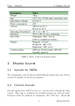
Table shows some basic technical specification of Digi.

1.3

Engine Time

When requested, Digi can be equipped with internal memory device
to count engine time. This is usually required when Digi is the only
device, which connects to the Daqu EMS box.

4

©

Kanardia

2017

Summary of Contents for Digi

Page 1: ...Digi Manual Kanardia d o o January 2020 Kanardia d o o Revision 1 0...

Page 2: ......

Page 3: ...ull license is available on http creativecommons org licenses by sa 3 0 legalcode web page and a bit more human readable summary is given on http creativecommons org licenses by sa 3 0 In short the li...

Page 4: ...sed using Gimp All document sources are freely available on request under the licence mentioned above and can be obtained by email Please send requests to info kanardia eu Revision History The followi...

Page 5: ...me 4 2 Display Layout 5 2 1 Layouts for OEMs 5 2 2 Custom Layouts 5 3 Installation Maintenance 6 3 1 Mounting Dimensions 6 3 2 Connections 6 3 2 1 CAN Bus CAN 7 3 2 2 Power POWER 8 3 3 Maintenance 9 3...

Page 6: ...engine monitoring display Device consists of electronics which captures the engine data from CAN bus and displays it on 4 3 inch sunlight readable LCD display The device itself is only 15 mm thick wh...

Page 7: ...onal 4 3 inch Resolution 480 x 272 Brightness 1000 cd m Communication CAN bus 29 bit header 500 kbit Kanardia protocol Table 1 Basic technical specifications 2 Display Layout 2 1 Layouts for OEMs The...

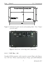
Page 8: ...ndroid device 3 Installation Maintenance 3 1 Mounting Dimensions Digi requires a 108 x 70 mm rectangular hole in the instrument panel The position of the hole must ensure that the instrument is always...

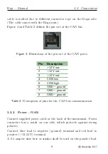
Page 9: ...ut and mounting holes Note Figure is not in scale Figure 2 Back view of the Digi with connections 3 2 1 CAN Bus CAN Standard RJ45 computer cable is used to connect Digi to the Kanar dia CAN bus When c...

Page 10: ...2 12V out 3 12V out 4 CAN low 5 CAN high 6 GND ground 7 GND ground 8 GND ground Table 2 Description of pins for the CAN bus communication 3 2 2 Power POWER Connect supplied power cable at the back of...

Page 11: ...rranty and the limited operation to get more information about the subject 4 1 Two Years Warranty Kanardia d o o warrants the Product manufactured by it against defects in material and workmanship for...

Page 12: ...plies only to hardware products manufac tured by or for Kanardia that have the Kanardia trademark trade name or logo affixed to them at the time of manufacture by Ka nardia The Limited Warranty does n...

Page 13: ...particular purpose non infringement and any war ranties against hidden or latent defects If Kanardia cannot lawfully disclaim statutory or implied warranties then to the extent permitted by law all s...

Page 14: ...no circumstances will Kanardia be liable for the provision of substitute goods or services Kanardia disclaims any representation that it will be able to repair any product under this warranty or make...

Reviews: