


Aetos Installation Manual
4. GNSS Antenna Installation
2
O
Ground from the system bus.
3
O
Ground from the backup battery.
4
O
Input power lead from backup battery.
5
O
Output power lead towards Aetos.
6
O
Ground lead towards Aetos.
7
O
Internal 10A fuse electronics fuse.
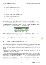
The following table shows approximate elapsed backup times
that were ob-
tained from 1.2 Ah 12 V battery for some typical configurations. Longer
elapsed time can be achieved by using a battery with larger capacity (2 Ah,
2.7 Ah, 3.4 Ah, . . . ) at the expense of weight increase.
Configuration
Time
Aetos and DAQU
37 min
Aetos, DAQU, Digi
TBD
Table 1:
Backup times achieved on a full 1.2 Ah battery at 22
◦
C. All instru-
ments running at 100% brightness.
Reducing the LCD brightness level significantly increases backup times.
4
GNSS Antenna Installation
The GNSS system in Aetos consists of two parts: the GNSS module and GNSS
antenna. The module is an integral part of the AD-AHRS-GNSS device, which
is built in the Aetos and the antenna cable connects to the back side of the
Aetos.
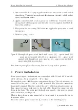
Standard SMA male connector is used on the antenna coaxial 50 Ω cable to
connected to the Aetos, Figure 12.
For the most reliable performance, the antenna requires a clear view of the sky.
The supplied antenna shall be mounted inside the cockpit on a place, which
will give the best 360
◦
view of the sky. Top of the instrument panel, below the
windscreen is a typical place. Try to meet the following recommendations:
2
Elapsed time when equipment is running solely on the power from backup battery.
20
©
Kanardia
2019–2020