Kami D201 Installation Manual Download Page 15

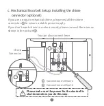
Youconnecteachofthewirestoeitherofthescrewsintheback.The
orderdoesnotmatter.
Ifyourwiresaretooshortandyouhavetroubleconnectingthewires
comingoutofthewalltothe
backofthedoorbell,please
usetheincludedExtension
Wiresandwirenuts.
(SeePicture).

g.


ConnectingtheDoorbellwiresand(2)ExtensionWires

(optional)

14

13

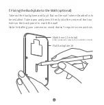
Feedallwires(andwirenuts,ifyouusethem)intothewallanduse
fourscrews(screwC)tosecureyourdoorbelltoFlatBackplate#1.

h.MounttheDoorbelltotheFlatBackplate

FlatBackplate#1

ScrewC

Pleasemakesurethe
powerforthedoorbell
isshutdownwhileyou
completethewiring.

MounttheDoorbelltotheFlatBackplate

:

(

FineThreads

)

Summary of Contents for D201

Page 1: ...Doorbell Camera Installation Guide...

Page 2: ...Kami Doorbell Camera x 1 Charging Cable x 1 Manual x 1 Battery x 1 Backplate x 3 1 A x2 B x4 C x4 Screw Bag x 1 Chime Connector x 1 Installation Hardware x 1 Screwdriver x 2 Extension Wires x 2 Wire...

Page 3: ...2 Getting to Know Your Doorbell Camera Light Sensor Lens Microphone Speaker Doorbell Button Screw Slot Speaker 2 Tamper Button PIR Sensor...

Page 4: ...3 Reset Button Speaker Tamper Button Power Connector To reset the doorbell fast press the Reset Button less than 1 second...

Page 5: ...The indicator light will be red while charging and turn white when fully charged a Charge the Battery Power Indicator Press down on the face of the doorbell with your thumbs and pull the outer protec...

Page 6: ...to the battery compartment as shown Ensure that the battery is inserted in the correct direction with pins facing up Push the tab shown in the diagram below to free the battery Pull the battery straig...

Page 7: ...the following voice prompts QR code scan is successful connecting to Wi Fi and Wi Fi is connected Step 4 After logging in to your Kami Home YI Home App tap the symbol in the top right corner and sele...

Page 8: ...es a digital chime you will need to install a diode If you are using a mechanical indoor doorbell DO NOT install a diode as this will damage the existing doorbell b Electronic Doorbell Setup Installin...

Page 9: ...t want chime to make a sound please connect the wires as shown in the picture c Mechanical Doorbell Setup Installing the chime connector optional Please make sure the power for the doorbell is shut do...

Page 10: ...Camera is 0 4m 0 13ft Additionally we recommend you install the doorbell at a height of 1 2m 4ft to ensure the ground in front of your door can be captured d Height and Distance Recommendations Camera...

Page 11: ...e Suggested Installation Angle Flat Backplate 1 Horizontal Angle Backplate 2 If you don t want to change the camera s angle use Flat Backplate 1 If you want to angle your Doorbell to the left or righ...

Page 12: ...to this installation mark Take out the backplane and lay it at on the wall where Doorbell is to be installed Take a pen and press it rmly into the center of the two holes in the back panel to mark th...

Page 13: ...12 Flat Backplate 1 Horizontal Angle Backplate 2 Vertical Angle Backplate 3...

Page 14: ...ort and you have trouble connecting the wires coming out of the wall to the back of the doorbell please use the included Extension Wires and wire nuts See Picture g Connecting the Doorbell wires and 2...

Page 15: ...uts if you use them into the wall and use four screws screw C to secure your doorbell to Flat Backplate 1 h Mount the Doorbell to the Flat Backplate Flat Backplate 1 Screw C Mount the Doorbell to the...

Page 16: ...15 Angled Backplate 2 or Backplate 3 Screw B Horizontal Angle Backplate 2 Mount the Doorbell to an Angled Backplate Course Threads...

Page 17: ...16 2 Screw A I Install the Front Panel 1 Use Screw A to keep the Doorbell Front Panel in place 2 Use Mounting Screw A to x the camera 1 Battery Tapered Head Torx...

Page 18: ...To complete the installation process please switch the power back ON and test the operation of your Doorbell j Turning the Power On Push up Switch the circuit breaker of the doorbell back to ON 17...

Page 19: ...which can be determined by turning the equipment o and on the user is encouraged to try to correct the interference by one or more of the following measures Reorient or relocate the receiving antenna...

Page 20: ...D201 V2 2 Website www kamihome com E mail support kamihome com https kamihome com legal fcc...

Reviews: