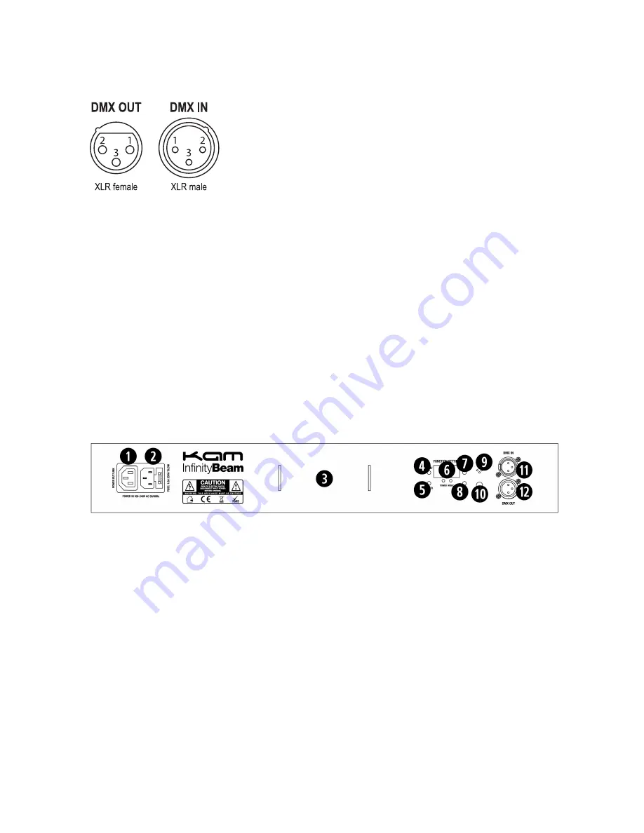
DMX-512 connection
If you are using a standard DMX controller, you can connect the DMX output of the controller directly to the DMX input of the first
unit in a DMX chain. If you wish to connect a DMX controller with other XLR outputs you will need to use adapter cables.
1 = ground 2 = minus signal (-) 3 = plus signal (+)
Connect the DMX output of the first unit in a DMX chain with the DMX input of the next unit in the chain. Always connect the the
output of one unit with the input of the next unit until all units are connected. If you use a controller with 5 pin DMX connection you
will need to use a 5 pin to 3 pin adapter.
Overhead rigging
Important
- the installation must be carried out by qualified service personal only. Improper installation can result in serious
injuries and /or damage to property. Overhead rigging required extensive experience. Working load limits should be respected,
certified installation materials should be used, the installed unit should be inspected regularly for safety.
l
Make sure the area below the installation place is free from unwanted persons during rigging, de-rigging and servicing.
l
Locate the unit in a well ventilated spot, far away from any flammable materials and/or liquids. The fixture must be fixed
at
least 50cm
from surrounding walls
l
The device should be installed out of reach of people and outside of areas where persons may walk by or be seated.
l
Before rigging make sure that the installation area can hold minimum point load of 10 times the device’s weight.
l
The device should be well fixed; a free swinging mounting is dangerous.
l
Do not cover any ventilation opening as this may result in overheating
Before first time use, the unit should be inspected for safety. Inspect the unit regularly every year.
Key to rear panel diagram
1.
Mains power output/link socket. Insert an IEC cable between this socket and a connected unit’s power input socket.
2.
Mains power input IEC socket. Connect the supplied IEC cable to the input and the mains power.
3.
Position of adjustable bracket
4.
Menu button – see below table for function setting
5.
Enter button – see below table for function setting
6.
Function setting LED display panel and LED indicators for power and sound input
7.
Down button – see below table for function setting
8.
Up button – see below table for function setting
9.
Microphone - used to monitor the music input during Sound-to-Light mode
10.
Sensitivity - used to adjust the mic’s input sensitivity during Sound-to-Light mode.
11.
DMX input - 3 pin male XLR socket for DMX communication
12.
DMX output - 3 pin female XLR socket for DMX communication
Rear panel Function Setting LED display
Use a combination of the four function buttons to set the unit to your desired working mode.
To select any of the menu options, press the MENU button to select the mode required.
Once you have made a selection then press ENTER to confirm.
Use the UP and DOWN buttons to choose the desired menu option.
The menu structure is shown on the following page.


