background image

10 

6.1.2.  House Heating/Cooling

including Buffer tank


1


Heat pump


7


Plate heat exchanger


13


Check valve


2


Flexible pipe


8


Buffer tank


14


Floor heating valve


3


Thermometer


9


Expansion tank


15


Floor heating pipe/fan coil unit


4


Manometer


10


Relief valve


5


Shut-off valve


11


Air vent valve


6


Y type water filter


12


Water pump for floor heating


6.2.  Choose a right heat pump unit 

(1)  Based on the local climate condition, construction features and insulation level, 

calculate the required cooling(heating) capacity per square meter. 

(2)  Conclude the total capacity which will be needed by the construction. 

(3)  According to the total capacity needed, choose the right model by consulting 

the heat.   

(4)  Pump features as below: 

a. Cooling only unit: chilled water outlet temp. at 5-15

, maximum ambient temp.

at 43

b. Heating and Cooling unit: for cooling chilled water outlet temp. at 5-15

,

maximum ambient temp. at 43

. For heating, warm water outlet temp. at 

9-75

, minimum ambient temp. at -25

c. Unit application

Inverter air source water heat pump is used for house, office, hotel, and so 

forth, which need heating or cooling separately, with each area needed to 

be controlled. 

6.3.  Installation Method 

The heat pump can be installed onto the concrete basement by expansion 

screws, or onto a steel frame with rubber feet which can be placed on the 

ground or housetop. 

Summary of Contents for R290 Series

Page 1: ...INSTALLATIONMANUAL AIR TO WATER HEAT PUMP SERIES R290...

Page 2: ...MODEL KHX 14PY3 KHX 16PY3 Air to Water Heat Pump Installation Manual...

Page 3: ...t 1 Preface 1 2 Safety Instructions 2 3 Features 5 4 Unit Dimension mm 6 5 Installation Diagram 7 6 Handling Installation 9 7 Maintenance 16 8 Parameters 19 9 Wiring Diagram 21 10 Display Operation Gu...

Page 4: ...tions are adhered to at all times to keep the warranty The unit can only be opened or repaired by a qualified installer or an authorized dealer Maintenance and operation must be carried out according...

Page 5: ...refully and understand the following information correctly Mark Meaning WARNING A wrong operation may lead to death or grievous injury on people ATTENTION A wrong operation may lead to harm to people...

Page 6: ...strange smells the power supply needs to be shut off to stop the unit Continue running may cause short circuit or fire Move and Repair Meaning Entrust When the heat pump needs to be moved or installed...

Page 7: ...Installation Place The unit CANNOT be installed near the flammable gas Once there is any leakage of the gas fire may occur Fix the unit Make sure that the basement of the heat pump is strong enough to...

Page 8: ...the heat pump Centralized controlling system can control several units by PC 3 2 Nice Appearance The heat pump is designed with beautiful looking The monoblock one has the water pump included which is...

Page 9: ...6 4 Unit Dimension mm 4 1 Models KHX 14PY3...

Page 10: ...a main circulation pump built inside When install the unit installers should connect the heat pump with other parts including the buffer tank for space heating cooling storage water tank for domestic...

Page 11: ...ss to the ozone sphere c Heating in frigid environment Optimized designed unit can achieve the heating function normally even when the ambient temperature is 25 d Infusing refrigerant The Heat Pump ar...

Page 12: ...heat pump 1 Heat pump 10 Relief valve 19 PT valve 2 Flexible pipe 11 Air vent valve 20 Electrical heater 3 Thermometer 12 Water pump for floor heating 21 Hot water sensor 4 Manometer 13 Check valve 5...

Page 13: ...l be needed by the construction 3 According to the total capacity needed choose the right model by consulting the heat 4 Pump features as below a Cooling only unit chilled water outlet temp at 5 15 ma...

Page 14: ...ll of high pressure nitrogen or keep it in a vacuum instead please follow these steps to infusing refrigerant R290 1 Preparations 4 Vacuumize the heat pump Connect the vacuum pump with the valve 2 kee...

Page 15: ...p 5 The flow switch is installed inside of the heat pump check to ensure that the wiring and action of the switch is normal and controlled by the controller 6 Try to avoid air stayed inside of the wat...

Page 16: ...s are open 2 Check the water loop to ensure that the water inside of the expansion tank is enough the water supply is good the water loop is full of water When the unit needs to be hung up during inst...

Page 17: ...l be 0 2 MPa on the water pressure meter 2 When the water pump runs for 1 minutes the compressor will start Hear whether there is strange sound from the compressor If abnormal sound occurs please stop...

Page 18: ...r Ensure the water refill and exhaust device in the waterway is well otherwise the performance and reliability of the unit will become worse Ensure the waterways are clean and avoid dirt and blockage...

Page 19: ...fire and explosion Ensure that space is sufficiently aerated around the product Preparation Before maintenance please ensure that the unit stop running and cut off the power supply Inspection and clea...

Page 20: ...duct using a sponge and hot water with a cleaning agent Do not use abrasive cleaners Do not use solvents Do not use any cleaning agents that contain chlorine or ammonia 7 3 3 Checking the evaporator f...

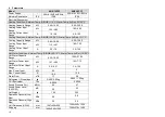
Page 21: ...12 4 47 1 80 7 30 Heating Current Input Range A 2 0 7 9 3 2 12 9 Hot Water Condition Ambient Temp DB WB 20 15 C Water Temp In Out 15 55 C Hot Water Capacity Range kW 6 50 18 50 10 00 27 00 Hot Water...

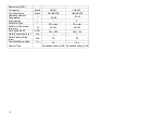
Page 22: ...Temperature 25 43 25 43 Fan Quantity 1 2 Fan Motor Type DC motor DC motor Fan Motor Power Input min max W 60 120 60 160 Fan Speed RPM RPM 220 600 300 750 Water Connection inch inch 1 1 Water Pressure...

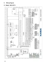
Page 23: ...9 1 Model KHX 14PY3 9 Wiring Diagram 20...

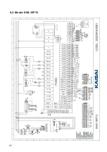
Page 24: ...21 9 2 Model KHX 16PY3...

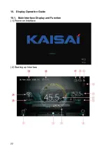
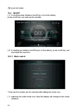
Page 25: ...22 10 Display Operation Guide 10 1 Main Interface Display and Function 1 Power on Interface 2 Starting up Interface...

Page 26: ...ing the main interface 3 is tank water temperature The machine is in hot water mode when this icon is shown Otherwise this icon is not shown 6 is outlet water temperature or room temperature If H25 0...

Page 27: ...off key can start up the machine 2 In starting up interface on off key is in blue status press on off key can shut down the machine 10 2 1 Mode switch There are five modes can be selected after slidi...

Page 28: ...ter function the key of hot water mode function will not be displayed In the main interface there are five modes that can be selected after tapping the mode key 1 tapping hot water mode icon then the...

Page 29: ...troller back to main interface 2 Sliding 2 the target temperature can be adjusted in the clockwise or counter clock wise direction 3 Tapping 3 the target temperature can be saved 10 3 1 Unlock screen...

Page 30: ...ed 10 4 Setting interface display and function Swipe from right to left on the main interface to enter the function setting interface and swipe from left to right on the function setting interface to...

Page 31: ...s parameters interface 3 Curve key Click this key to view the temperature curve 4 Adjust brightness Click this button to adjust screen brightness 5 Fault Click to view fault history One key electric h...

Page 32: ...nitialized to the time at the moment when the system time setting button is pressed and you can adjust the time by sliding up and down Note When the temperature unit is the time format is displayed as...

Page 33: ...t from 0 00 23 59 The mute timer off setting point select from 0 00 23 59 The status of mute timer on Enable Blue Disable Gray The status of mute timer on is shown The status of mute timer off Enable...

Page 34: ...lected and saved every five minutes Timekeeping is made from the latest data saving if the power is disrupted when the time is less than five minutes the data during such period will not be saved 3 On...

Page 35: ...tness setting value 3 The screen has the function of automatic on and off if there is no operation for 30s the screen will enter the half time screen state 4 If there is no operation for another 5 min...

Page 36: ...10 5 Status interface display Swipe from left to right on the main interface to enter the status interface and swipe from right to left on the status interface to return to the main interface The stat...

Page 37: ...e Fault name Occurrence time of the fault Day an month hour minute second Note If the current temperature is occurrence time of the fault Month and day hour minute second Click this key to clear all f...

Page 38: ...35 V202109HH01...

Page 39: ...NOTE...

Page 40: ...kaisai com 20220425 0003...

Reviews: