background image

12

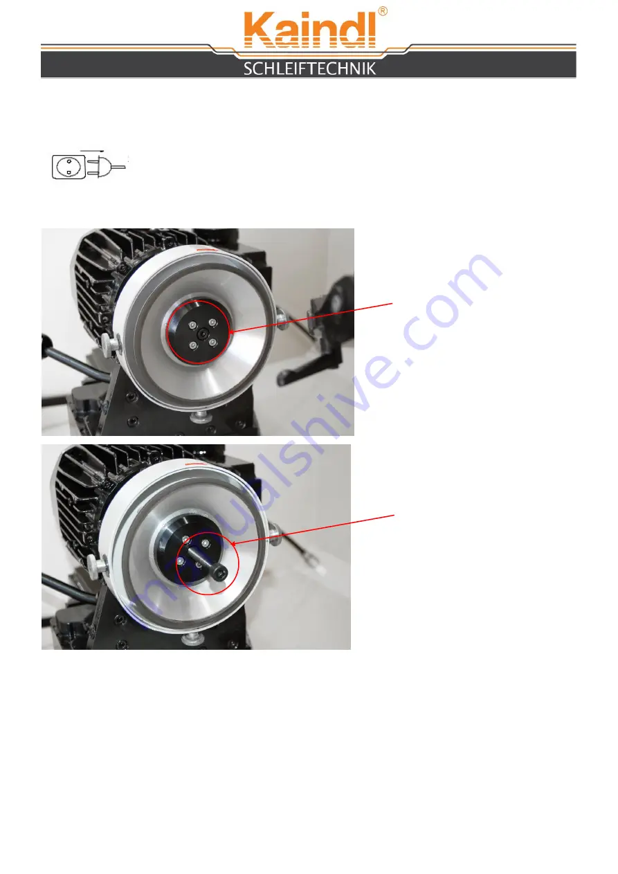
First unplug from electric current!

Unscrew the allen screw M6 with the supplied allen wrench SW 5.

Screw in the lifting screw M8 for lifting the grinding wheel support with the grinding wheel.

Place the new grinding wheel on the motor shaft and pay attention that the driving pin of 
the grinding wheel support is placed in the groove of the motor shaft. 

Now tighten the grinding wheel support with an allen wrench. 

8. 

CHANGE


OF


THE


GRINDING


WHEEL

Imperatively also remove the circular knife before!

Open the hexagon 
screw M6

Screw in the lifting 
screw M8 for lifting the 
grinding wheel support 
with the grinding wheel

Summary of Contents for RMS Series

Page 1: ...ING MACHINE RMS MANUAL Original operation manual Please keep for further use Kaindl Schleiftechnik REILING GmbH Remchinger Str 4 D 75203 Königsbach Stein Germany Tel 49 7232 4001 0 Fax 49 7232 4001 30 Internet www kaindl de E Mail info kaindl de ...

Page 2: ...nife 7 Adjustment of the circular knife 8 Grinding of the circular knife 9 Basic regrading grinding Important information please read 10 Standard values for sharpening operation 11 Operation of the manual version 12 Change of the grinding wheel 13 Description of the cooling unit Basic information about cooling liquids 14 Change of knife support Spare part list 15 Maintenance Cleaning Repairs Dispo...

Page 3: ...g EC instructions EC Instruction EMV 2004 108 EC Applied harmonises norms EN ISO 12100 1 and EN ISO 12100 2 EN 294 EN ISO 13732 1 EN 61029 1 EN 60204 Part 1 EN 61000 6 1 EN 61000 6 2 EN 61000 6 3 EN 61000 6 4 Changes in design which affect the technical data listed in this manual and the directed use therefore change the machine substantially make this declaration of conformity invalid The documen...

Page 4: ...on top of the cabinet and align in booth direction by adjusting the machine feet Please pay attention that the place of the machine grants a vibration free operation 1 3 GENERAL SAFETY ADVICE Read the operating manual intensive For damages caused by ignorance or not following the operating manual no liability is assumed When dealing with circular and shape knife greatest caution is needed because ...

Page 5: ...2 STRUCTURE 5 Grinding motor Cooling Safety cover Grinding wheel cover Clamping flange round knife Driving motor Lynette Adjustment bridge Adjustment pillar ...

Page 6: ... Electronical Data Drive of grinding spindle Motor 1 230V 50 Hz Motor speed 2770 RPM Power 0 37 KW IP code IP 55 Flow time of the mounted grinding wheel approx 10 sec Coolant pump Motor 1 230V 50 Hz Power Step 1 0 028 KW Step 2 0 045 KW Step 3 0 063 KW IP code IP 65 Delivery rate 16 35 l min Drive of circular knife Specifications are subject to change 6 Only of the manual version Continiuously var...

Page 7: ... and loosening of the circular knife Risk of injury 4 OPERATION 4 1 FIXATION OF THE ROUND KNIFE Pressure disk Clamping nut Shaft fixation Shaft Lynette Clamping flange After you have fixed the circular knife place the lynette on the back of the knife Align the lynette in the way that the wheel is turning softly e g circular knife 10 lynette approx 15 Depending on the type of circular knife you can...

Page 8: ... knob screw to arrest the adjustment pillar Star knob screw to arrest the cutting angle 1 2 Hand lever for the adjustment of the grinding motor After you have set the angle open the star knob screw 2 and move the adjustment pillar in the way that the cutting edge of the round knife is inside the marked grinding range Grinding range ...

Page 9: ...e complete feeding size has been worked off Surely grinding also means scrub treatment but this is with it s parameters quite sobering for an amateur in grinding Scrubbing means very coarse grit open bonding of the grinding wheel feeding of max 12 µ halt periods of min 10 30 seconds at knife rotation of 15 to 25 rpm and a lot of cooling liquid As mentioned above these parameters are only a rough g...

Page 10: ...ng 8 µ Halt time 20 sec Spark time 100 sec Knife speed 18 Cooling liquid Emulsion 10 15 Finishing treatment Material High grade steel Abrasive CBN Grit size B 76 Feeding 4 µ Halt time 25 sec Spark time 120 sec 150 sec Knife speed 12 Cooling liquid Emulsion 10 15 Scrub treatment Material HSS harted steel Abrasive CBN Grit size B 252 Feeding 8 µ Halt time 20 sec Spark time 90 sec Knife speed 22 Cool...

Page 11: ...11 7 OPERATION MANUAL VERSION The feeding of the manual version is made with the handwheel placed on the left side of the machine ON OFF switch The machine only runs when the safety protection is closed ...

Page 12: ...w grinding wheel on the motor shaft and pay attention that the driving pin of the grinding wheel support is placed in the groove of the motor shaft Now tighten the grinding wheel support with an allen wrench 8 CHANGE OF THE GRINDING WHEEL Imperatively also remove the circular knife before Open the hexagon screw M6 Screw in the lifting screw M8 for lifting the grinding wheel support with the grindi...

Page 13: ...e top level of the pump Electric plug for cooling unit on the back of the cabinet Important information regarding cooling liquid Only use water soluble emulsions on mineral oil base By use synthetic products the painting and plastic parts can be damaged We will not accept any responsibility for these damaged When proving the cooling liquids pay attention to the directives of the manufacturer Pleas...

Page 14: ... screw For changing the support loosen with the supplied allen wrench SW 5 the allen screw M6 Screw in the provided allen screw M8 and lift the support from the cone 11 WIRING DIAGRAM The wiring diagram is placed in inside the control cabinet behind the door ...

Page 15: ... and plug for damage For preventing corrosion provide blank and blue steel parts with a slight film of oil Important The protective cover plates of the machine protect the guidances spindles and switches below from dirt and cooling liquid So when cleaning the machine with the cooling liquid gun do not undermine these protective cover plates 14 REPAIRS Repairs on the machine can only be carried out...

Page 16: ...am parameter assignment Damage by use of force Damages and consequential damages caused by breach of the duty of taking care of the user damages caused by aggressive detergents as corrosive or caustic cleaning materials solvents etc or aggressive cooling lubricants In case of a warranty claim we ask you to inform us about the type serial No and year of construction of the machine Without informati...

Page 17: ...ble 4 Grinding wheel 13 Star knob screw for fixation 5 Grinding wheel support 14 Star knob screw with bolt 6 Support for circular knife 15 Cover plate feeding unit 7 Lynette bearing 16 Cover sheet 8 Lynette support 17 Adjustable drive motor controlling 9 Drive motor for circular knife 18 On Off switch 17 SPARE PART LIST RMS MANUELL 1 2 3 4 8 7 11 12 5 6 9 10 14 13 15 16 18 17 ...

Page 18: ...18 ...

Page 19: ...19 ...

Reviews: