background image

5

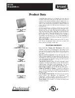
1.  Temperature Indicator

2.  Operator Interface Display

3.  Power-on Light

4.  Compressor-on Light

5.  Alarm / Service Light

6.  Schedule On/Off and Enter Button

a.  In display mode: Press to toggle between 

SCHEDULE RUNNING and MANUAL OVERRIDE.

b.  In program mode:

i.  Press to move to a lower level menu.

ii.  Press to accept a value that has been edited.

7.  Program Mode (i) and Esc

a.  In display mode: Press and hold to enter program 

mode.

b.  In program mode: Press to move to a higher level 

menu.

8.  Up Arrow

a.  In display mode: No function

b.  In program mode:

i.  Press to view the next item in a list or to 

increment a variable to a higher value.  Press 

and hold for accelerated incrementing.

ii.  When the top of the list (or highest value) is 

displayed, pressing the up button will cause 

the display to wrap to the bottom of the list (or 

lowest value).

9.  Down Arrow

a.  In display mode: No function

b.  In program mode:

i.  Press to view the previous item in a list or to 

increment a variable to a lower value.  Press and 

hold for accelerated incrementing.

ii.  When the bottom of the list (or lowest value) is 

displayed, pressing the down button will cause 

the display to wrap to the top of the list (or 

highest value).

10.  1/0: Press at any time to turn the dryer on/off.
11.  Drain test: Press at any time to momentarily the open 

drains (like the current emm).

12.  Reset: Press at any time to clear the alarm/service 

message (if shown) and the alarm LED.

CONTROL PANEL

1

2

3

4

5

6

7

8

9

10

11

12

causes the solenoid core 

(3)

 to move, closing the pilot air 

supply line and opening the pilot air exhaust line.  After 

the pilot air above the diaphragm 

(4)

 is vented, pressure 

in the reservoir opens the discharge port and forces 

the condensate through the discharge port and outlet 

piping.

2.0 OPERATION

2.1  Minimum/Maximum operating conditions

A.  Maximum inlet air pressure:  refer to dryer serial number 

tag

B.  Minimum inlet air pressure:  30 psig (2.1 kgf/cm

2

C.  Maximum inlet air temperature:  120°F (49°C)
D.  Maximum ambient temperature:  

Air-cooled models:  110°F (43°C)


Water-cooled models:  130°F (54°C)

E.  Minimum ambient temperature:  45°F (7°C)

2.2  Start-up

A.  Energize dryer.  Green power on light will illuminate.

IMPORTANT:  Energize dryer disconnect switch (provided 

by others, see NEC) 24 hours before refrigeration 

compressor is started!  Never use the disconnect switch 

to shutdown the dryer for a extended period of time 

(except for repair).  Failure to follow these instructions 

may result in a non-warrantable compressor failure.


NOTE:  If there is no power to the control board for 

a period of two weeks or more, it may return to the 

default mode.

B.  Program Monitor
Press and hold Program Mode button until Main Menu screen 

appears.  Use the Up and Down arrow buttons to scroll 

through the list of submenu choices.  Press Enter button to 

view the submenu that is displayed.  Press ESC to exit the 

Main Menu and return to Display mode.
1.  Language selection

a.  Use the ‘Up’ and ‘Down’ arrow buttons to scroll 

through the list of languages (choice of 10 available: 

English, Deutsch, Francais, Espanol, Italiano, Polski, 

Dansk, Dutch, Norsk and Suomi).

b.  Press ‘Enter’ button to select the language that is 

displayed.

c.  Push ‘ESC’ at any time to return to the Main Menu. 

1

2

3

4

Summary of Contents for TF 171E

Page 1: ...NG 2 1 0 INSTALLATION 3 2 0 OPERATION 5 3 0 MAINTENANCE 8 SIZING 8 ENGINEERING DATA 9 WIRING DIAGRAM Model TF 171E 10 11 Model TF 210E 12 13 575 460 3 60 Transformer Pack 14 DIMENSIONS WEIGHTS 15 TROU...

Page 2: ...our plant It was received in good condition by the carrier and was so acknowledged Check for Visible Loss or Damage If this shipment shows evidence of loss or damage at time of delivery to you insist...

Page 3: ...d 45 to 130 F 7 to 54 C E Installations in altitudes above 4500 feet 1370 meters Dryer is adjusted to operate in altitudes up to 4500 feet 1370 meters If dryer is installed in an altitude above this a...

Page 4: ...manual draining convenient dryer depressurization and EDD service a three way valve assembly has been installed at the bottom of the moisture separator and cold coalescing filter where applicable Rev...

Page 5: ...the pilot air supply line and opening the pilot air exhaust line After the pilot air above the diaphragm 4 is vented pressure in the reservoir opens the discharge port and forces the condensate throug...

Page 6: ...m on or off use On Off button Push Schedule On Off and Enter button to return to schedule NOTE After power interruption dryer will reenergize in Manual override refrigeration system off To restart Sch...

Page 7: ...contact on the compressor contactor is open when the dryer is off TEMP SENSOR Occurs if the temperature sensor circuit is open or shorted If open the left most LED in the temperature display will be i...

Page 8: ...tiply the rated capacity from Table 1 by the multipliers shown in Table 2 Example How many scfm can an air cooled model TF 171E handle when compressed air to be dried is at 200 psig and 100 F ambient...

Page 9: ...psig 9 3 barg Required Available Water Pressure Differential 40 psig 2 8 barg minimum Flow Required with 85 F Cooling Water gallons per minute 60 Hz 4 9 6 8 50 Hz 4 1 5 6 Electrical Data Nominal Volta...

Page 10: ...only FAN 2 HARNESS FPS 2 FAN 2 REF SHEET 02 LINE 11 REF SHEET 02 LINE 10 REF SHEET 01 LINE 20 03 10 11 12 09 08 07 06 05 04 L3 L3 L3 L2 L2 02 01 00 PE TB1 L1 L2 L3 L1 L1 L1 L2 L3 CONT 1 PE TB2 T1 T2 T...

Page 11: ...5 W13 W14 W11 W10 W9 W8 W21 W19 Alarm B N C Alarm B Com Drain Test Output Alarm B N O Drain Test Output Compressor 1 Output Compressor 1 Output W27 W18 W17 W16 N A N A W25 W23 FROM SHEET 01 01 03 02 0...

Page 12: ...HEATER 1 FAN 2 HARNESS FPS 2 FAN 2 REF SHEET 02 LINE 11 REF SHEET 02 LINE 10 REF SHEET 01 LINE 20 03 10 11 12 09 08 07 06 05 04 L3 L3 L3 L2 L2 02 01 00 PE L1 L1 L1 L2 L3 TB1 L1 L3 L2 CONT 1 DISCONNECT...

Page 13: ...5 W13 W14 W11 W10 W9 W8 W21 W19 Alarm B N C Alarm B Com Drain Test Output Alarm B N O Drain Test Output Compressor 1 Output Compressor 1 Output W27 W18 W17 W16 N A N A W25 W23 FROM SHEET 01 01 03 02 0...

Page 14: ...14 WIRING DIAGRAM 575 460 3 60 Transformer Pack...

Page 15: ...25mm ELECTRICAL ENTRY 750 19mm RS 232 ACCESS 0 25 NPT DRAIN CONNECTION MODEL TF171E 0 25 NPT DRAIN CONNECTION MODEL TF210E Dimensions inches mm Model TF 171E TF 210E A 58 06 1475 58 06 1475 B 32 15 81...

Page 16: ...enser cooling Air cooled Ambient temperature too high clogged condenser fins obstructed flow across condenser faulty fan motor or fan control switch Water cooled Cooling temperature too high flow too...

Page 17: ...30763 Hot Gas By Pass Valve Air Cooled 5002351 5002351 5002351 5002351 Filter Dryer Liquid Line 5002925 5002925 5002925 5002925 Temperature Sensor 3210926 3210926 3210926 3210926 Contactor 5002926 500...

Page 18: ...18 NOTES...

Page 19: ...19...

Page 20: ...price of the product or part THE FOREGOING WARRANTY IS EXCLUSIVE AND IN LIEU OF ALL OTHER WARRANTIES WHETHER WRITTEN ORAL OR STATUTORY AND IS EXPRESSLY IN LIEU OF THE IMPLIED WARRANTY OF MERCHANTABIL...

Reviews: