10 Fault Recognition and Rectification
10.1 Basic information
The following tables are intended to assist in locating the causes of faults.
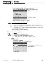
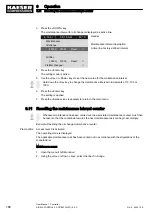
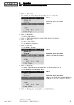
There are three types of fault indicated in the SIGMA CONTROL 2:
■ Fault with the machine:
The
red LED flashes, the machine shuts down: see chapters 10.2 and 10.5.
■ Fault with the controller:
The machine shuts down, see chapter 10.6.
■ Warning:
The
yellow LED illuminates, the machine does not shut down: see chapter 10.3.
The messages valid for your machine are dependent on the controller and the individual equipment
specification.
1. Do not attempt any fault rectification measures other than those specified in this operating
manual!
2. In all other cases:
Arrange for the fault to be rectified by an authorised service partner.
10.2 Interpreting alarm messages
If an input signal is classified as a fault, the controller will display an alarm upon receiving the
signal.
Consequences:
■ The
red LED flashes:
■ The controller shuts the machine down.
Alarm messages are indicated with the letter A.
Messages are not numbered consecutively.
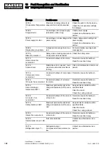
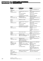
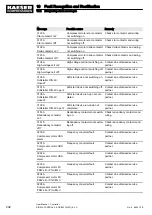
In this table, “%d” represents a variable value, e.g. a number, period of time or I/O address.
1)
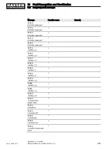
Messages 0073-0078 and 0081-0098 are customer-specific.
Add in the meaning for the message text you have defined (see chapter 8.12).
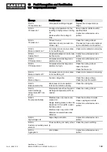
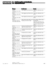
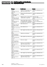
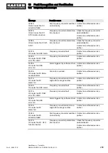
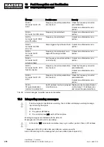
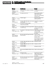
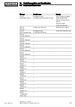
Message
Possible cause
Remedy
0001 A
Direction of rotation
Compressor motor turning in
wrong direction.
Reverse supply lines L1 and L2.
0002 A
Motor temperature ⇞
Compressor motor too hot.
Keep ambient conditions within
specified limits.
Check the cooling air supply.
Clean the motor.
0003 A
pRV ⇞
Safety valve actuating pressure on
oil separator tank exceeded.
Replace the safety valve.
0004 A
EMERGENCY STOP
EMERGENCY STOP command
device actuated.
Unlock the keys.
10 Fault Recognition and Rectification
10.1 Basic information
No.: 9_9450 12 E
User Manual Controller
SIGMA CONTROL 2 SCREW FLUID ≥5.0.X
197

