background image

2.12  Network Conditions

The machines listed in table are intended for operation with a public power supply with a network

impedance at the transfer point (house connection) of maximum Z

max

  [Ohm].

The operator must ensure that the machines are only connected to a supply network that meets these

requirements.
The local electricity utility will provide information on the network impedance.

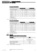
2.12.1  Mains conditions at 400V/3/50Hz

Model

Start configuration

Starts [1/h]

Z

max

 [Ω]

EPC 150–2

Direct online

20

0.767

Star-delta

EPC 230–2

Direct online

20

0.360

Star-delta

1.266

EPC 420–2

Direct online

15

0.099

Star-delta

0.366

EPC 550–2

Direct online

15

0.077

Star-delta

0.280

EPC 750–2

Direct online

15

0.048

Star-delta

0.178

EPC 1000–2

Direct online

15

0.029

Star-delta

0.104

Tab. 25 Network impedance

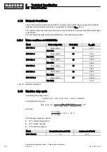
2.13  Machine duty cycle

Calculating the cycling period:

Cycling   time   =   time   under   load   +   time   at   standstill

Calculating the duty cycle:

Duty   cycle   [%]   =

time   under   load

time   under   load   +   standstill   time

x   100

Example

12   minutes
20   minutes

x   100   %   =   60   %

The following values are valid for:
■ 20 °C ambient temperature
■ 30 % relative humidity
■ 1013 mbar air pressure

Model

Permissible duty cycle

2

 [%]

Cycling period

1

 [min]

EPC 150-2-G

≤ 70

3–30

2

Technical Specification

2.12 Network Conditions

12

Assembly and operating manual    2-stage piston compressor  
EPC-2-G  

No.: 9_5753_04 E

Summary of Contents for EPC 1000-2-G

Page 1: ...bly and operating manual 2 stage piston compressor EPC 2 G No 9_5753_04 E Manufacturer KAESER KOMPRESSOREN GmbH 96410 Coburg PO Box 2143 GERMANY Tel 49 0 9561 6400 Fax 49 0 9561 640130 http www kaeser...
Page 2: ...Original instructions KKW PEPC 1 04 en SBA KOLBEN AGGREGAT 2 STUFIG...

Page 3: ...Basic Information 14 3 2 Specified Use 14 3 3 Improper use 14 3 4 User s responsibilities 14 3 4 1 Observe statutory and universally accepted regulations 14 3 4 2 Defining personnel 15 3 4 3 Inspecti...

Page 4: ...35 6 7 2 Anchoring the Machine 38 6 7 3 Mounting the machine on a compressed air tank 38 6 8 Retrofitting the Sound Enclosure accessory 39 6 8 1 Dismantling the sound enclosure 39 6 8 2 Vent the mach...

Page 5: ...nging the solenoid valve 61 10 14 Cylinder head and valves 61 10 14 1 Checking the cylinder head and valves 61 10 14 2 Cleaning the cylinder head and valves 62 10 14 3 Starting the machine and carryin...

Page 6: ...Contents iv Assembly and operating manual 2 stage piston compressor EPC 2 G No 9_5753_04 E...

Page 7: ...mounts 38 Fig 17 Securing the bolt on machine mounts 38 Fig 18 Removing the air filter 39 Fig 19 Fitting the Sound Enclosure 40 Fig 20 Switching on and off 45 Fig 21 Cleaning the air cooler or fan gu...

Page 8: ...List of Illustrations vi Assembly and operating manual 2 stage piston compressor EPC 2 G No 9_5753_04 E...

Page 9: ...ply details 690V 3 50Hz 9 Tab 20 Supply details 230V 3 60Hz 10 Tab 21 Supply details 380V 3 60Hz 10 Tab 22 Supply details 440V 3 60Hz 11 Tab 23 Supply details 460V 3 60Hz 11 Tab 24 Connection details...

Page 10: ...List of Tables viii Assembly and operating manual 2 stage piston compressor EPC 2 G No 9_5753_04 E...

Page 11: ...le directives Missing documents can be requested from KAESER Make sure all documents are complete and observe the instructions contained in them Make sure you provide the data from the nameplate when...

Page 12: ...avoid dangerous situations This symbol is is placed by lists of actions comprising one stage of a task In lists of actions with several stages the sequence of actions is numbered This symbol is is pl...

Page 13: ...le contains a list of possible options Enter options here as a reference Option Option code Available Oil level monitor C5 Adjustable machine mountings H1 Silenced air filter H9 Air filter with plasti...

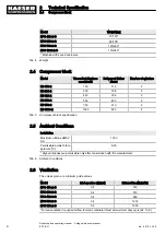
Page 14: ...s Installation Maximum altitude AMSL m 1000 Permissible ambient tem perature C 5 35 Higher altitudes are permissible only after consultation with the manufacturer Tab 6 Ambient Conditions 2 6 Ventilat...

Page 15: ...essure of the cylinder relief valve EPC 420 2 bis EPC 1000 2 Activating pressure of the air cooler relief valve EPC 420 2 bis EPC 1000 2 Maximum working pres sure bar 15 Activating pressure bar 17 5 T...

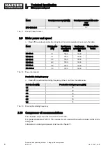
Page 16: ...1500 1800 Tab 12 Power and speed Permissible starting frequency Read off the permissible starting frequency of the motor from the table below Rated power kW Permissible starting frequency 1 h 1 1 20...

Page 17: ...essor Cool to moderate ambient temperatures low humidity low to average duty cycle Tab 14 Compressor oil recommendations 2 10 1 Compressor oil charge Model Total charge litres Topping up volume litres...

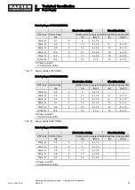
Page 18: ...3 and IEC 60364 4 473 and DIN VDE 0298 4 standards for 30 C ambient temperature and wiring type C For other application conditions check conductor diameters and change accordingly Cables laid side by...

Page 19: ...y cable mm2 Backup fuse A Supply cable mm2 150 2 G 2 2 6 4 x 1 5 230 2 G 3 2 10 4 x 1 5 6 4 x 1 5 420 2 G 5 2 10 4 x 1 5 6 4 x 1 5 550 2 G 8 0 16 4 x 2 5 10 4 x 1 5 750 2 G 9 6 20 4 x 2 5 10 4 x 1 5 1...

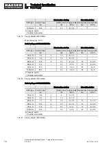
Page 20: ...7 4 35 4 x 6 20 4 x 2 5 750 2 G 21 0 50 4 x 10 25 4 x 4 1000 2 G 28 0 63 4 x 16 35 4 x 6 Pressure switch Controller star delta Tab 20 Supply details 230V 3 60Hz Rated voltage 380V 10 3 60Hz Direct onl...

Page 21: ...y cable mm2 Backup fuse A Supply cable mm2 150 2 G 2 3 6 4 x 1 5 230 2 G 3 5 6 4 x 1 5 420 2 G 5 9 16 4 x 2 5 10 4 x 1 5 550 2 G 8 7 16 4 x 2 5 10 4 x 1 5 750 2 G 10 5 25 4 x 4 16 4 x 2 5 1000 2 G 15...

Page 22: ...420 2 Direct online 15 0 099 Star delta 0 366 EPC 550 2 Direct online 15 0 077 Star delta 0 280 EPC 750 2 Direct online 15 0 048 Star delta 0 178 EPC 1000 2 Direct online 15 0 029 Star delta 0 104 Tab...

Page 23: ...230 2 G 70 3 30 EPC 420 2 G 70 4 30 EPC 550 2 G 70 4 30 EPC 750 2 G 70 4 30 EPC 1000 2 G 70 4 30 Tab 26 Machine duty cycle 2 Technical Specification 2 13 Machine duty cycle No 9_5753_04 E Assembly and...
Page 24: ...s service manual Operate the machine only within its performance limits and under the permitted ambient condi tions Do not use compressed air for breathing purposes unless it is specifically treated D...

Page 25: ...e received adequate training in and authorization for the safe installation and mainte nance of this machine Ensure that personnel entrusted with operation installation and maintenance are qualified a...

Page 26: ...machine power Check regularly that all electrical connections are tight and in proper condition Forces of compression Compressed air is contained energy Uncontrolled release of this energy can cause s...

Page 27: ...sulation Use hearing protection when appropriate The pressure relief valve blowing off can be particularly loud Operating fluids materials Strictly forbid fire open flame and smoking Follow safety reg...

Page 28: ...requirements with regard to explosion protection are in force For instance the requirements of ATEX directive 94 9 EC Equipment and Protective Systems intended for use in Potentially Explosive Atmosp...

Page 29: ...a 1 m radius of the machine Operating personnel Maintenance Within the machine Within a 1 m radius of the machine Maintenance personnel Tab 28 Danger Areas 3 6 Safety Devices Various safety devices en...

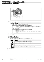
Page 30: ...e Wear long sleeved garments not synthetics such as polyester and protective gloves Tab 29 Safety Signs 3 8 Information signs The table lists the various information signs used and their meanings Symb...

Page 31: ...general terms and condi tions of business apply with regard to warranty A condition of our warranty is that the machine is used for the purpose for which it is intended under the conditions specified...

Page 32: ...This applies particularly to parts contaminated with compressor oil Drain condensate into a receptacle Obtain advice from KAESER on suitable drains and receptacles Do not allow operating materials to...

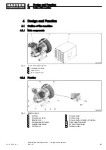
Page 33: ...1 Air filter 2 Compressor block 3 Electric motor 4 Compressed air cooler 5 Cylinder relief valve 6 Oil filler port 7 Oil sight glass 8 Oil drain plug 9 Arrow showing direction of rotation 10 Compresse...

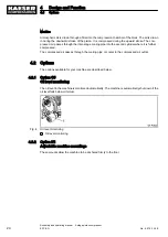
Page 34: ...pipe or cooler to the compressed air outlet 4 2 Options The options available for your machine are described below 4 2 1 Option C5 Oil level monitoring The oil level in the machine is monitored automa...

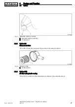
Page 35: ...evel of the machine It also cleans the inlet air Fig 6 Silenced air filter 1 Air filter element 4 2 4 Option H10 Air filter with plastic casing This air filter is suitable for unfavourable ambient con...

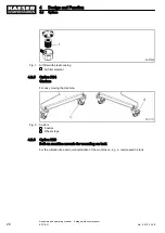
Page 36: ...ne Fig 8 Castors 1 Castors 2 Wheel stops 4 2 6 Option H20 Bolt on machine mounts for mounting on tank For the vibration free and quiet installation of the machine on e g a compressed air tank 4 Design...

Page 37: ...lenoid valve and the oil level monitoring Option C5 This enables an unloaded starting of the machine The control unit is not provided with the machine and is to be supplied by the user The following p...

Page 38: ...overload protection The motor protection device shuts down the machine in the case of a phase drop out overload if the ambient temperature becomes too high if the compressor block seizes if the mains...

Page 39: ...ined with regard to ambient temperature and humidity clean inlet air with no damaging contaminants inlet air free of explosive or chemically unstable gases or vapours inlet air free of acid alkaline f...

Page 40: ...without danger or hindrance 5 2 2 Ensuring adequate ventilation If the ventilation is insufficient a partial vacuum can be created in the room 1 Ensure that the volume of air flowing into the machine...

Page 41: ...d air network the network working pressure may not exceed the permissible working pressure of the machine Please contact KAESER for advice 5 Installation and Operating Conditions 5 2 Installation cond...

Page 42: ...ressed air system to ensure that no compressed air can flow back into the machine 2 Vent all pressurized components and chambers completely 3 The pressure gauge on the machine must read 0 bar Working...

Page 43: ...ssed air connection 1 Flexible hose 2 Shut off valve 3 Check valve A shut off valve and check valve must be installed by the user in the connection line Make the connection to the air main by a flexib...

Page 44: ...pply Precondition The machine is disconnected from all power supply phases The disconnecting device is locked in the off position A check has been made that no voltage is present 1 Have the power supp...

Page 45: ...disconnecting device and check that no voltage is present 6 Connect the machine to the power supply 6 7 Options The options available for your machine are described below 6 7 1 Option C5 Oil level mon...

Page 46: ...el 1 The user is to make the connection to the power supply or the connection to an external control unit 2 The machine is switched off by the external controller 6 7 1 1 Float switch The float switch...

Page 47: ...f fatal injury caused by contact with live components Switch off and lock out the power supply disconnecting device and verify the absence of voltage 2 Open the switch cover 3 Loosen the screw and mov...

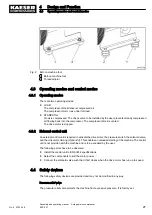
Page 48: ...ing in chapter 13 2 6 7 3 Option H20 Mounting the machine on a compressed air tank Fig 17 Securing the bolt on machine mounts 1 Bolt on machine foot 2 Threaded joint 3 Hex head bolt 4 Hexagon nut Use...

Page 49: ...in the off position A check has been made that no voltage is present The machine is completely depressurised pressure gauge reads 0 bar The machine has cooled down The user s shut off valve between t...

Page 50: ...Fitting the Sound Enclosure 1 Compressor block 2 Base plate 3 Machine mounting pad 4 Air cooler 5 Hose 6 User s check valve 7 Sheet metal ring 8 Pre cut foam 9 Air inlet soundproofing box 10 Sound enc...

Page 51: ...orking on pressure systems 1 Close shut off valves or otherwise isolate the machine from the compressed air system to ensure that no compressed air can flow back into the machine 2 Vent all pressurize...

Page 52: ...specifications on the nameplate 2 1 Are the power supply cable conductor diameters and fuse ratings ad equate 2 11 Have all electrical connections been checked for tightness Repeat check after 50 ope...

Page 53: ...motor overload protection device This phase current is 0 58 times the rated motor current see motor nameplate The overload protection device setting can be 10 higher than the rated phase current to p...

Page 54: ...ime the compressor takes to fill the air receiver when new can be useful in checking the machine s performance at a later date Precondition Machine at operating temperature 1 Close the shut off valve...

Page 55: ...us injury is possible The machine restarts automatically when power is restored after a power cut Make sure that no one is working on the machine Switch the machine on and off according to the start c...

Page 56: ...witch on the machine from the external control unit Result The machine starts as soon as network pressure is lower than the cut out pressure Switching off 1 Switch off the machine from the external co...

Page 57: ...he cut out pressure Switching off 1 Switch off the machine from the external control unit 2 Switch off and lock out the power supply isolating device 8 Operation 8 1 Switching on and off No 9_5753_04...

Page 58: ...e trip in the user s pressure switch or the controller Machine starts with difficulty The solenoid valve is not open ing Check the connection to the sol enoid valve Change the solenoid valve Bearing d...

Page 59: ...user s pres sure switch while the machine is running Defective switch diaphragm Replace the pressure switch The venting valve is not closing Clean or replace the venting valve Whistling sound from th...

Page 60: ...can flow back into the machine 2 Vent all pressurized components and chambers completely Working on the drive system 1 Switch off and lock out the power supply disconnecting device and check that no...

Page 61: ...Regular maintenance tasks 10 2 3 Oil change interval Duty cycles and ambient conditions are important criteria for the number and length of the oil change intervals Advice can be obtained from KAESER...

Page 62: ...3 Maintaining the air cooler or fan guard According to machine model it either has an air cooler of a fan guard Clogging causes overheating and machine damage Regular cleaning ensures reliable coolin...

Page 63: ...ce is switched off the device is locked off a check has been made that no voltage is present The machine has cooled down Fig 22 Air filter maintenance 1 Air filter 2 Inlet air opening 3 Air filter ele...

Page 64: ...dirt to ingress the pressure system and cause damage to the machine Material Compressed air for blowing out Spares as required Precondition The supply disconnecting device is switched off the device...

Page 65: ...e housing and sealing faces 5 Replace the filter element 6 Position the cover and close the retaining clips 7 Switch on the power supply disconnecting device 10 6 Option H10 Air filter with plastic ca...

Page 66: ...the housing and sealing faces 5 Replace the filter element 6 Replace the cover and screw down tight 7 Switch on the power supply disconnecting device 10 7 Drive Motor Maintenance The drive motor beari...

Page 67: ...f the machine and check visually for leaks 10 10 Changing the compressor oil The initial charge of oil should be changed as specified in table 36 Drain the oil completely from the compressor block If...

Page 68: ...machine and check the oil level again after about 2 minutes topping up again if nec essary 4 Switch off the machine and check visually for leaks 10 11 Testing the pressure relief valve To check the va...

Page 69: ...re relief valve anticlockwise until air blows off 2 Then turn the knurled knob back to its original position Pressure relief valve does not blow off Have the defective relief valve replaced by KAESER...

Page 70: ...ystem Material Compressed air for blowing out Cleaning rags Acid free grease e g Shell Retinax Replacement part Precondition The mains disconnecting device is switched off The disconnecting device is...

Page 71: ...n is correct as indicated by the arrow on the body 4 Screw the fitting and damper into the new solenoid valve using sealing tape 5 Re install the solenoid valve in the compressed air line 6 Open the u...

Page 72: ...ne and the air network is closed 1 Remove the cylinder head screws and lift off the head 2 Remove the cap nut if one is fitted 3 Clean the cylinder head and valves 4 After cleaning the cylinder head a...

Page 73: ...e and service work carried out in the list Date Maintenance task carried out Operating hours Signature Tab 40 Logged maintenance tasks 10 Maintenance 10 15 Document maintenance and service work No 9_5...

Page 74: ...ating fluids materials may damage the ma chine or impair its proper function Personal injury may result from machine damage Use only original KAESER parts and operating fluids materials Have an author...

Page 75: ...y as all regulations are kept to Why not sign a KAESER AIR SERVICE maintenance agreement Result Your advantage lower costs and higher compressed air availability 11 4 Service Addresses Addresses of KA...

Page 76: ...low the machine to cool down completely 2 Spray the valves and cylinder bore with Shell Ensis 20 preserving oil The oil does not need to be removed when re commissioning 3 Disconnect all air and elect...

Page 77: ...or lifting gear with personnel trained in the safe transport of goods Make sure the danger zone is clear 12 4 2 Transporting with a forklift truck Precondition Machine must stand on a suitable transpo...

Page 78: ...2 5 Disposal When disposing of a machine drain out all liquids and remove dirty filters Precondition The machine is decommissioned 1 Completely drain the oil from the machine 2 Remove old filters 3 Ha...

Page 79: ...nnex 13 1 Pipeline and instrument flow diagram P I diagram 13 Annex 13 1 Pipeline and instrument flow diagram P I diagram No 9_5753_04 E Assembly and operating manual 2 stage piston compressor EPC 2 G...
Page 80: ...13 Annex 13 1 Pipeline and instrument flow diagram P I diagram 70 Assembly and operating manual 2 stage piston compressor EPC 2 G No 9_5753_04 E...

Page 81: ...13 Annex 13 1 Pipeline and instrument flow diagram P I diagram No 9_5753_04 E Assembly and operating manual 2 stage piston compressor EPC 2 G 71...
Page 82: ...13 2 Dimensional Drawing 13 Annex 13 2 Dimensional Drawing 72 Assembly and operating manual 2 stage piston compressor EPC 2 G No 9_5753_04 E...

Page 83: ...13 Annex 13 2 Dimensional Drawing No 9_5753_04 E Assembly and operating manual 2 stage piston compressor EPC 2 G 73...

Page 84: ...13 Annex 13 2 Dimensional Drawing 74 Assembly and operating manual 2 stage piston compressor EPC 2 G No 9_5753_04 E...

Page 85: ...13 Annex 13 2 Dimensional Drawing No 9_5753_04 E Assembly and operating manual 2 stage piston compressor EPC 2 G 75...

Page 86: ...13 3 Electrical diagram 13 Annex 13 3 Electrical diagram 76 Assembly and operating manual 2 stage piston compressor EPC 2 G No 9_5753_04 E...

Page 87: ...13 Annex 13 3 Electrical diagram No 9_5753_04 E Assembly and operating manual 2 stage piston compressor EPC 2 G 77...

Page 88: ...13 Annex 13 3 Electrical diagram 78 Assembly and operating manual 2 stage piston compressor EPC 2 G No 9_5753_04 E...

Page 89: ...13 Annex 13 3 Electrical diagram No 9_5753_04 E Assembly and operating manual 2 stage piston compressor EPC 2 G 79...

Page 90: ...13 Annex 13 3 Electrical diagram 80 Assembly and operating manual 2 stage piston compressor EPC 2 G No 9_5753_04 E...

Page 91: ...13 Annex 13 3 Electrical diagram No 9_5753_04 E Assembly and operating manual 2 stage piston compressor EPC 2 G 81...

Page 92: ...13 Annex 13 3 Electrical diagram 82 Assembly and operating manual 2 stage piston compressor EPC 2 G No 9_5753_04 E...

Page 93: ...13 Annex 13 3 Electrical diagram No 9_5753_04 E Assembly and operating manual 2 stage piston compressor EPC 2 G 83...

Page 94: ...13 Annex 13 3 Electrical diagram 84 Assembly and operating manual 2 stage piston compressor EPC 2 G No 9_5753_04 E...

Page 95: ...13 Annex 13 3 Electrical diagram No 9_5753_04 E Assembly and operating manual 2 stage piston compressor EPC 2 G 85...

Page 96: ...13 Annex 13 3 Electrical diagram 86 Assembly and operating manual 2 stage piston compressor EPC 2 G No 9_5753_04 E...

Reviews: