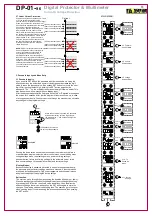
3.2 Protection Program Selection
the first menu that comes is the protection program selection.
The Program must be chosen according to the system
-
Prog 1
System protection program, when selected Prg1 led turns on.
( check 1.1.1 section)
-
Prog 2
Motor protection program, when selected Prg2 led turns on.
( check 1.1.2 section)
-
Prog 3
Full protection program, when selected Prg1 and Prg2 leds turn on.
( check 1.1.3 section)
3.3 Alarm Control Menu
S
Increase
Decrease
3.2 Protection
Program
selection
S
Increase
Decrease
S
Increase
Decrease
S
Decrease
S
S
Increase
Decrease
S
Increase
Decrease
S
Increase
Decrease
S
Increase
Decrease
S
Increase
Exit
Digital Protector & Multimeter
Current & Voltage Protection
DP-01-
96
®
ALr/CtrL :
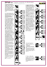
Alarms can be activated or deactivated in this menu and it is related to the
output relay. For example; the occurance of an activated alarm switches off
the output relay, with the related alam led blinking. If a deactivated alarm
occures, the output relay does not switch off the output relay, only the related
alarm led blinks.for this reason the operator must carefully which alarms would
be avtivated and which would be deactivated. In automatic mode, when the
alarm count reach the limit value within the specified period, the system will be
locked and the related alarm led and current or voltage led (maybe both) blink.
To know which alarm occurred operator should use the direction buttons to
reach the related alarm (current, voltage or maybe both) and observe the
failure phase.
Resetting The Alarm:
While functioning in the manual mode, if an alarm occurs (an activated alarm)
then the relay switches off the output contact with the related alarm led
blinking. To reset the device the operator must push the SET button until the
reset led goes off. The thing that must be awared of is that if the opeator
releases the set button before the reset button turns off accidently, the main
menu entry shows on, the operator has two options then; the first option is to
enter the password (no matter the entry is wrong or correct) the use the
direction buttons to reach the quit command and press SET button, the second
option is to wait for four minutes without pushing any button.If the related
alarm led turns off again after a long push of the SET button, it means that the
alarm situation is still present.In automatic mode, if the alarm count reaches
the limit value within the specified period, the system will be blockedas it does
in the manual mode. After fixing the problem, the operator must push the SET
button to reset the device.
Aust :
When the over current alarm's (Aust) value is (1) it is active, when (0) it is
not active. The occurance of an over current alarm while Aust is activated
switches off the output relay. When Aust is deactivated it does not control
the output relay, it only makes the related alarm led blinks.
AaLt :
When the under current alarm's (AaLt) value is (1) it is active, when (0) it is
not active. The occurance of an under current alarm while AaLt is activated
switches off the output relay. When AaLt is deactivated it does not control
the output relay, it only makes the related alarm led blinks.
When Prg1 or Prg2 is selected, the AaLt will not be shpwn on the menu.
AaSy :
When the asymmetric current alarm's (AaSy) value is (1) it is active, when (0)
it is not active. The occurance of an asymmetric current alarm while AaSy is
activated switches off the output relay. When AaSy
is deactivated it does not control the output relay, it only makes
the related alarm led blinks.When Prg1 is selected, the AaLt will
not be shown on the menu.
quIt :
To exit the menu.
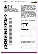
I f the current and voltage output
relays are going to be used
individually the Alr/out Value
should set to “0000”.
The connection way is shown in
the Figure next.
If the current and voltage output
relays are going to be used
together, the Alr/out Value should
set to “0001”and the Com
terminal must not be used.
Unless both of the voltage and
current failures fixed the output
relays will stay in the switch off
mode. The connection way is
shown in the figure next.
Com
Volt
current
Phase
Neutral
Neutral
Com
Volt
current
Phase
Neutral
A
Lr
/o
u
t v
a
lu
e“
0
00
1”
(r
e
la
te
d)
A
Lr
/o
u
t
va
lu
e
“
0
00
0”
(I
n
di
vi
d
ua
l)
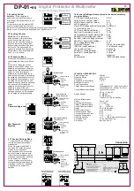
ALr/out:
It shows the relays' (current and voltage relays) behaviour after passing the
alarm situation.
Uust :
When the over voltage alarm's (Uust) value is (1) it is active, when (0) it is
not active. The occurance of an over voltage alarm while Uust is activated
switches off the output relay. When Uust is deactivated it does not control
the output relay, it only makes the related alarm led blinks.
UaLt :
When the under voltage alarm's (UaLt) value is (1) it is active, when (0) it is
not active. The occurance of an under voltage alarm while UaLt is activated
switches off the output relay. When UaLt is deactivated it does not control
the output relay, it only makes the related alarm led blinks.
UaSy :
When the asymmetric voltage alarm's (UaSy) value is (1) it is active, when
(0) it is not active. The occurance of an asymmetric voltage alarm while
UaSy is activated switches off the output relay. When UaSy is deactivated
it does not control the output relay, it only makes the related alarm led
blinks.


