Kaco blueplanet 3.0 NX1 M2 Manual Download Page 10


KACO blueplanet 3.0 NX1 M2   KACO blueplanet 3.7 NX1 M2 KACO blueplanet 4.0 NX1 M2 


KACO blueplanet 5.0 NX1 M2


                                                                                                   Page 8  


1.11


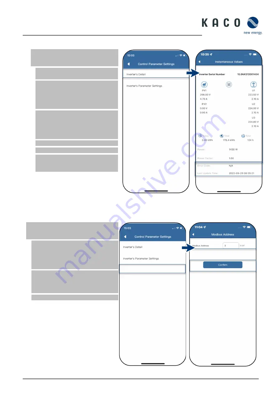
Viewing the instantaneous values 


Under <Available Inverters>, select the 

desired device and open the <Inverter 

Values & Settings> menu. 


1. Select <Momentary values> and view 

information about the installation. 


Note: 

All measured values for your PV 

system and the grid power are 

displayed. In addition, the daily and yield 

values are displayed according to solar 

feed-in.


Note: 

The measured values are only 

displayed for the selected unit. The 

evaluation of all inverters can only be 

carried out via our "blueplanet web" 

monitoring portal. 


2. View current power and power factor 


3. View pending errors via <Error Code>.  


Note:

 In the event of a pending error, 

please refer to the 

error code 

list in 

chapter 7.1 on page 31


Fig. 26.


view instantaneous values 

Fig. 27.


Overview of performance values


1.12


View Modbus Address 


Under <Available Inverters>, select the 

desired device and open the <Inverter Values 

& Settings> menu. 


Note:

 By default, the Modbus address "3" 

is stored here and should not be changed 

for an inverter. This value is used for the 

communication for data loggers and smart 

meters. 


1. If necessary, enter a new value for each 

additional inverter that follows the first 

communication device and confirm the 

entry <Confirm>. 


»

 Modbus address configured. 


Fig. 28.


Select Modbus address 

Fig. 29.


Set mode address


Summary of Contents for blueplanet 3.0 NX1 M2

Page 1: ...is application note lies solely with KACO new energy GmbH Application Note installation and use of the APP English translation of German original Authorised electrician Important safety instructions A...

Page 2: ...e WLAN configuration 12 3 2 Displaying details of the WLAN connection 12 3 3 Reset faulty connection 13 3 4 Changing network 13 3 5 APN Setting 14 4 Configuring parameters 15 4 1 Authorisation to chan...

Page 3: ...led note of the required peripheral equipment in order to implement an optimum solution for your specific application Step 1 Communication device Set up via mobile terminal Fig 1 Access via APP to a d...

Page 4: ...horisations to record the user s telephone data NOTE Our KACO homepage offers a wide range of further product information to assist you during start up You can find this information in the download ar...

Page 5: ...hot spot WLAN is established B0 Fig 6 Select Commissioning Fig 7 Scan QR code on communication device Note The connection exists exclusively via the hotspot until step 6 This is how long your mobile...

Page 6: ...ice to the customer WLAN Fig 11 Connection to the customer WLAN network is established Note Network Configuration displays information on the unit serial number software version and system time If the...

Page 7: ...on 1 Execute action steps 1 4 are from chapter 1 5 on Page 3 2 Execute the hotspot connection via Confirm 3 Note the checklist and status Process takes up to 5 min Successful connection is displayed i...

Page 8: ...pter 4 on page 15 Fig 18 Communication device in the local network Fig 19 Communication device in the customer WLAN network 1 8 Set up time zone Note The time transmitted by the network is GMT time Yo...

Page 9: ...country and network type according to network operator requirements and confirm with OK 3 Activate additional functions via enable functions see chapter 4 2 on page 16 Note By default all required pa...

Page 10: ...out via our blueplanet web monitoring portal 2 View current power and power factor 3 View pending errors via Error Code Note In the event of a pending error please refer to the error code list in chap...

Page 11: ...ng mode of the communication device Communication device is registered in the customer WLAN network and the router is connected to the Internet Note The device supports Modbus TCP and the usual SunSpe...

Page 12: ...k of your mobile device must match that of the communication device If you still cannot find the communication device you can switch off the router and connect directly via the hotspot Fig 34 Select O...

Page 13: ...connected 4 Toggle on the Enable Feed in Control when the meter is connected 5 Via Maximum Feed in Power set in watts the maximum power which the device may feed into the grid Note This setting is on...

Page 14: ...ls of the WLAN connection Communication device Properties opened via Communication device 1 First check the quality via Signal Strength of the WLAN connection Note Interference free communication can...

Page 15: ...unit Fig 46 Note for Reset communication device 3 4 Changing network Communication device opened 1 Open the Network Properties menu The currently connected router is then displayed 2 Enter the passwo...

Page 16: ...this must be set here Usually however the APN is created automatically as soon as a SIM card is inserted Open Communication Device 1 Open the APN setting 2 enter your provider under APN Examples can...

Page 17: ...arameters for the initial commissioning Attention No password is required for initial parameterization However if the parameters of the unit need to be changed after initial commissioning it is necess...

Page 18: ...tive Power Limit Details see Chapter 6 on page 28 Active Power Ramp See Chapter 4 8 on page 19 P U See chapter 4 10 on page 21 P f See chapter 4 9 on page 20 Reactive Power Control See chapter 4 11 on...

Page 19: ...settings Grid parameters set Fig 57 Connection Conditions Fig 58 Set connection conditions 4 4 Trip Voltage Settings Note There are three threshold values for overvoltage and undervoltage protection T...

Page 20: ...eshold third minimum threshold Trigger time for the first threshold trigger time for the second threshold trigger time for the third threshold 3 Confirm all settings Frequency protection defined Fig 6...

Page 21: ...of the device can be permanently set to a value lower than the max output power via the active power settings This may be necessary in order to limit the maximum connected load of the unit at the grid...

Page 22: ...e active power as a percentage of Pn the inverter provides non hysteresis in the control of active power response to over frequency 2 Variable gradient and non hysteresis P is the active power as a pe...

Page 23: ...ive power as a percentage of Pn the inverter provides non hysteresis in the control of active power response to overvoltage 2 Variable gradient and non hysteresis P is the active power as a percentage...

Page 24: ...be necessary to meet the requirements of a first order filter Reactive power type defined Fig 77 Set Settling time Fig 78 Select reactive power settings and select after Settling time Fig 79 Choose o...

Page 25: ...n menu Setting for 1 Select Cos Phi Constant Setting menu 2 Set fixed displacement factor 3 Select phase 4 Confirm all settings Cos phi constant defined Fig 81 Select Cos phi constant settings Fig 82...

Page 26: ...ating voltage Note Activation threshold as a percentage of Un corresponds to the Lock In voltage 3 Define Deactivating voltage Note Deactivation threshold as a percentage of Un corresponds to the Lock...

Page 27: ...hold as a percentage of Pn corresponds to the Lock In voltage 3 Define Deactivating power as a of Pn Note Deactivation threshold as a percentage of Pn corresponds to the Lock Out voltage Q U curve def...

Page 28: ...e of the communication device Note The communication device provided is required in order to carry out the update The firmware update can only be carried out with adequate DC power 100 W The current f...

Page 29: ...t the tab Inverter and press Local upgrade to call up the inverter device 3 In the firmware path locate and open the file masterVxxx xxxxx xx bin The upload begins 6 Open Local upgrade for the Safety...

Page 30: ...or data logger must be connected so that the feed in limit of 70 can be raised The total consumption is transmitted to the inverter data logger by the additional Smart Meters per phase so that it can...

Page 31: ...hand must ensure that no electricity is fed into the public grid Depending on self consumption the PV system output may be switched on in order to use the generated energy oneself and thus not have to...

Page 32: ...necting additional consumers heating water or energy storage systems the self consumption and thus the utilization of the PV electricity can be significantly increased However this function can only b...

Page 33: ...arts up the cause may be an internal short circuit in the communication cable No Description Step AC DC terminals melted 1 It is necessary to tighten the connection firmly when attaching the terminals...

Page 34: ...aused by the grid voltage If the measured voltage is normal please switch the isolator switch on and continue with the next step 3 Measure the AC voltage UL1 N UL2 N UL3 N UN PE using a multimeter 4 I...

Page 35: ...es that the DC input voltage exceeds the maximum DC voltage of the inverter 2 Remove all strings from the inverter and use the multimeter to measure the voltage between PV and PV for each string The t...

Page 36: ...Werner von Siemens Allee 1 74172 Neckarsulm Germany Tel 49 7132 3818 0 info kaco newenergy de www kaco newenergy com 3015474 05 221004...

Reviews: