


9
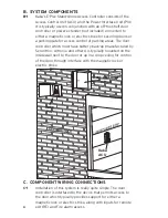
C-2
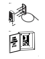
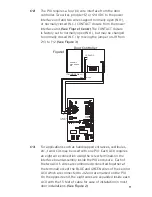
The PIU requires a four (4) wire interface from the door
controller. Two wires p12 or +24 VDC to the power
interface unit and two wires support normally open (N.O.),
or normally closed (N.C.) CONTACT closure from the power
interface unit.
(See Figure 1 below)
The CONTACT closure
is factory set to normally open (N.O.), but may be changed
to normally closed (N.C.) by moving the jumper on J11 from
2->3 to 1->2.
(See Figure 3)
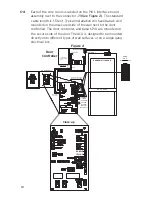
C-3
For applications such as handicapped entrances, vestibules,
etc., two ACUs may be used with one PIU. Each ACU requires
an eight wire connection using the screw terminals on the
interface board assembly inside the PIU enclosure. Each of
the two ACU’s wires are commoned (connected together at
the terminal) except the BLUE and GREEN wires of the second
ACU which are connected to J12 and are marked on the PIU.
On the opposite end, the eight wires are expanded inside each
ACU with the 1.5 feet of cable for ease of installation in most
door installations.
(See Figure 2)
+
-
12-24 VDC
(ON INSIDE WALL)
ALTRONIX,
SECURITRON,
ETC.
RED
BLACK
POWER FROM
ALARM BOX
Figure 1
Door Controller
YELLOW
PURPLE
Summary of Contents for E-PLEX 5x70 Series
Page 1: ...1 E PLEX 5x70 Series Stand Alone Access Controller Installation Instructions...
Page 9: ......
Page 12: ......