Kaba E-Plex 5x00 Cylindrical Installation Instructions Manual Download Page 10

15

14

Note:

For security reasons, all existing audit events are not deleted.

The lock is now set to the factory-configured setup with the default factory

master code, 1,2,3,4,5,6,7,8. Important: Before you can program the lock

you must first enter a new 8 digit master code of your choice.

For example, if your new code is 1,3,5,7,2,4,6,8, the correct buttons to

press in the exact order are:

#1,2,3,4,5,6,7,8,#,0,0,0,#,1,3,5,7,2,4,6,8,#,1,3,5,7,2,4,6,8,#,#

To determine if you have successfully changed your master code, enter

1,3,5,7,2,4,6,8, and the lock should open. Now try the factory master

code, 1,2,3,4,5,6,7,8, and the lock should not open.

Refer to the included Operations Manual for further programming

instructions.

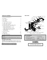
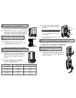
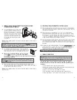
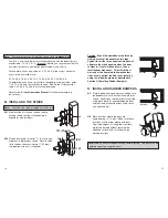
M. INSTALLING THE STRIKE

Note:

The latch and strike provided must be used.

M-1

Mark location of strike on the door frame,

making certain that the strike opening is

aligned (a) with latch bolt.

M-2

Mortise doorframe for strike

3

32

" (3 mm) deep

minimum to dimensions shown. Secure strike

(b) to the door frame using two 1" (25 mm)

combination screws (c) (supplied).

c

a

b

Correct

Incorrect

a

b

Caution: Check the operation of the latch by
making sure that the deadlatch (a) stops
against the strike (b) as shown and does not
slide into the strike opening when the door
is closed. If that situation occurs, then a
total lockout may occur. This will void our
warranty of the complete lock mechanism.
If necessary, correct the door over-travel by
using the rubber bumpers as described in
Section N (Installing Rubber Bumpers).

N. INSTALLING RUBBER BUMPERS

N-1

Close the door and apply pressure making sure

the deadlatch (a) rests on the strike plate (b) as

shown. Standing on the frame (door stop) side

of the door, check for gaps between the door

and the frame on the three sides of the frame

(left, right, and top).

N-2

Mark locations where the gaps are

approximately

3

16

" (5 mm). Make sure these

locations are free from grease and dust.

Peel the bumpers (c) (supplied) from their

protective backing without touching the

adhesive surface and stick them on the

marked locations.

Note:

Allow 24 hours for adhesive to set before testing. The door may be

operated normally during this time.

a

1

1

/

4

" (31mm)

b

c

4

7/8

" (124mm)

3

3

/

8

" (84mm)

Summary of Contents for E-Plex 5x00 Cylindrical

Page 1: ...5 x 0 0 C y l i n d r i c a l Installation Instructions...

Page 2: ...18 mm Screws Latch 1 25 mm Screws Security Screw Tool Set Screw Release Tool ASA Strike Battery Cover Screws The E Plex 5031 is a non handed lock that is preassembled for left hand installations It i...

Page 3: ...orter 13 8 35 mm connecting screws also supplied C 2 Reference Figure B For thicker door applications of 21 8 54 mm to 21 2 57 mm remove the two connecting screws a from the cylinder drive unit b Add...

Page 4: ...pressing latch bolt b in slightly until the outside unit assembly c rests flush against the door Ensure the red collar is seated in the top left mounting hole Note If the red collar appears to be too...

Page 5: ...tuted with a foreign part If the lock is used with a wall bumper the war ranty is null and void If a doorstop is required we recommend the use of a floor secured stop The environment and conditions of...

Page 6: ...oor Exercise Room This lock is New Installation Replacing a conventional keyed lock Replacing a Kaba Mechanical Pushbutton Lock Replacing a Kaba Electronic Access Control Replacing a Keyless Lock othe...

Page 7: ...nobs Secure the outside lever knob by rotating the key clockwise 45 degrees to the horizontal position Remove key 8 9 LH KIL Lever Sleeve RH f b b a a 45 G CHANGING KEY IN LEVER KNOB CYLINDER On key i...

Page 8: ...outside lever knob b and rotate it counterclockwise 45 degrees Insert release tool d into the small hole e under lever knob as shown Gently push lever catch up until it clicks Remove tool d then remov...

Page 9: ...push button on lock and then release the key 3 Red and green lights should begin flashing 4 Input 1 2 3 4 5 6 7 8 at lock within 10 seconds 5 You should hear sound of lock resetting and a high pitch...

Page 10: ...he door frame using two 1 25 mm combination screws c supplied c a b Correct Incorrect a b Caution Check the operation of the latch by making sure that the deadlatch a stops against the strike b as sho...

Page 11: ...Kaba Access Control 2941 Indiana Avenue Winston Salem NC 27105 USA Tel 800 849 8324 336 725 1331 Fax 800 346 9640 336 725 3269 www kabaaccess com www e plexlock com PKG2992 1206...

Reviews: