16
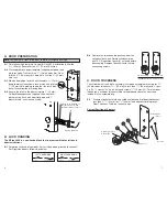
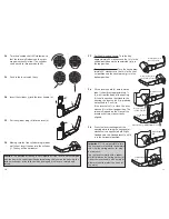
J. INSTALLING LOCK HOUSINGS
J-1
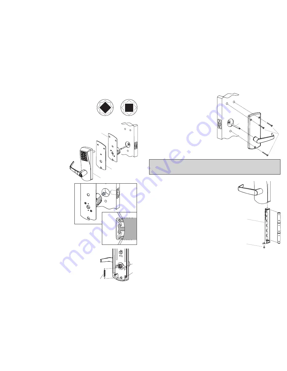
Insert the slotted end of the square spindle
into the outside lever hub until it locks, at an
angle of 45
º
. (The spindle can be removed
by pulling on it, if oriented incorrectly.)
J-2
Assemble gasket onto the out-
side housing (a). Assemble
cylindrical plate assembly
onto the outside lock housing.
J-3
Place the outside housing (a) and
cylindrical plate assembly on the
door so that spindle engages hub
of cylindrical unit of latch.
J-4
On the inside trim assembly, turn the lever to
the correct horizontal rest position for the
handing of the door. Install the tension spring
(l) between the handle (h) and the post (p).
(outside)
cylindrical
unit
latch
a
Gasket
Cylindrical Plate
Assembly
Square Spindle Position
correct
incorrect
h
p
l
17
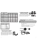
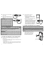
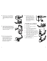
J-5
Place the inside trim assembly on
the door so that the spindles (o)
engage the inside lever. Fasten
to the outside housing using the
three
1
⁄
8
" (3 mm) hex drive
mounting screws (p).
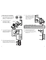
K. INSTALLING BATTERY PACK
Note: If the lock makes a continuous buzzing noise or the red LED lights
continuously, reset the electronics by removing the battery holder for ten
seconds, then reinsert it.
K-1 Three AA batteries should already be
installed in the battery holder (q).
K-2 Insert the battery holder into the outside
housing and secure it using the 6-32 x
5
⁄
16
"
(8 mm) screw (r).
p
o
q
r


