


Version 02/15/2016
Page 25 of 40
Mounting instructions 82132/3xxx CB 30
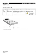
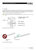
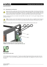
Boltwork connection: Possible via the two M4 threads in the bolt head available on the front side. Optionally via a pusher in
the bolt head (not included in the standard).
The bolt was according to EN1300 with a permanent load of 2,5 N over 10.000 cycles tested. These load should not be
exceeded permanently.
10.3
Lock interfaces
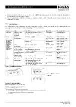
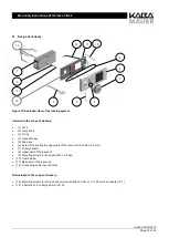
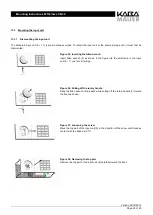
For a description of the interfaces at the lock, please refer to Table 7 below. The position of the sockets and their pin
assignment according to Table 7 can be found in Figure 25: Lock connectors.
Socket
Type
Description
Specification
Pin assignment
Input unit
Communication
line to the
input unit
Connection for connecting cable to
the input unit
6-pin socket
As pre-assigned
in/out
(required
connecting cable
can be ordered
from Kaba
Mauer under
the item no.
3002500193
if inputs
or outputs
are to be
used without
alarm box)
Lock
Output signal
Bolt position switch
Change-over
contact 30V DC /
0.1 A
Pin1= Common
Pin2= Normally Closed
Pin3= Normally Open
Silent alarm
3
Max. 24 V DC/
25 mA
Pin6= Collector
Pin7= Emitter
Lock
Input signal
(Only configurable
via the Combi B
30 configuration
software (only one
function each
possible; stan-
dard: disabled))
Remote control disable
12V DC +/-10 %
Pin4= +12V
Pin5= GND
Omission alarm
(min. actuation time 500 ms; opening
must take place within 60 s)
12V +/-10 %
See remote control
disable
OD/OST override
12V +/-10 %
See remote control
disable
Double code override
12V +/-10 %
See remote control
disable
Power
Permanent
power supply
Connection for optional Combi B 30
Kaba Mauer power supply unit
(item no. 3002501220)
9V
As pre-assigned
Connection for optional alarm box
4
(item no. 3001001550)
9V
As pre-assigned
Table 7: Overview connectors
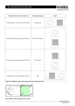
Figure 25: Lock connectors
Pin 1 Assignment of the connectors
3
only possible with Kaba Mauer alarm box
4
Power supply for lock and alarm box via the alarm box:
a)
when connected to signaling equipment without power supply option by means of an additional
12V power supply unit (item no. 3002501230)
at the alarm box or
b)
via the EMA
Pin 1 of the connector in
question