background image

For Professional Technical Support call 1-844-242-2475                                                                                                                          11 


PUMP PRIMING&STARTUP 


CAUTION: Risk of burns. 

Never run pump dry. Running pump without water may cause pump to overheat, damaging 

seal and possibly causing burns to persons handling pump. Fill pump with water before starting. 

WARNING: Risk of explosion and scalding. 

Never run pump against closed discharge. To do so can boil water inside 

pump, causing hazardous pressure in unit, risk of explosion and possibly scalding persons handling pump. 


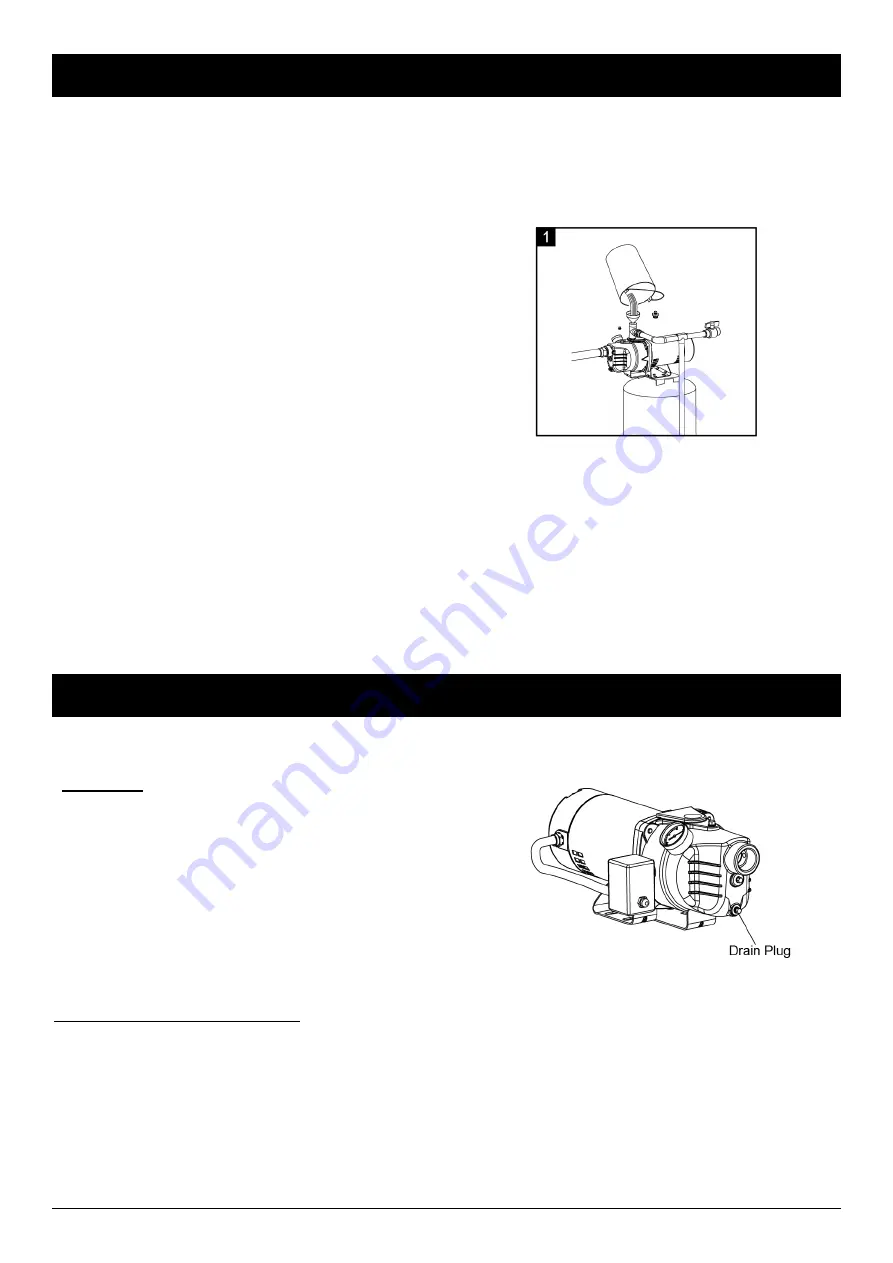
1.  Remove the priming plug or tee from the pump and fill 

the pump, fill all piping between the pump and the well, 
and make sure that all piping in the well is full. If you 
have also installed a priming tee in the suction piping, 
remove the plug from the tee and fill the suction piping. 
(Fig. 1)


2.  Replace all fill plugs, Open the faucet closest to the pump/tank a small amount to allow air to escape the system. 

3.  Power on! Start the pump.  

4.  I

f you don’t have water after 2 or 3 minutes, stop the pump and remove the fill plugs. Refill the pump and piping. You 

may have to repeat this several times in order to get all the trapped air out of the piping.  

5.  After the pump begins building pressure in the system, shut the faucet off. Let the pump build pressure until it shuts 

off. Check the pressure switch operation by opening a faucet or two and running enough water out to bleed off 

pressure until the pump starts. The pump should start when pressure drops to 30 PSI and stop when pressure 

reaches50 PSI. Run the pump through one or two complete cycles to verify correct operation. This will also help 

clean the system of dirt and scale dislodged during installation. 

If you were unsuccessful, please refer to Troubleshooting or call our customer service technical staff. 


CARE AND MAINTENANCE 

WARNING:

 Disconnect power and release all pressure from the system before attempting to install, service, relocate or 

perform any maintenance. 

Winterizing  

CAUTION:

  Drain  the  entire  system  if  there  is  danger  of 

freezing. A drain plug is provided at the bottom of the pump 
case for this purpose


Drain openings are provided on all models to drain the 
pump:  


 Unplug the pump from power supply outlet. 


Remove drain plug close to the inlet hole. 


Drain all piping to a point below the freeze line. This will 
drain the pump. 


NOTE

: While this will drain the pump, it will not necessarily drain all the unprotected parts of the piping system. To drain 

tank, disconnect the piping at the tank outlet. 

SEAL ASSEMBLY REPLACEMENT 
CAUTION: Make certain that the power supply is disconnected before attempting to service the unit! The rotary 
seal assembly must be handled carefully to avoid damaging the precision lapped faces of the sealing 
components. 

1. Disengage pump body (Ref. No. 1) (Include diffuser 4.venturi 3) from motor mounting ring (Ref. No. 8). 
2. Remove the rear cover(Ref. No. 11) .Remove the impeller(Ref. No. 5) use a 9/16" open end wrench to hold the motor 
shaft.  
3. The rotary seal (Ref. No. 6) will come loose at this time. Use a screwdriver (or similar instrument) to pry the silicon 
carbide seal from the recess of the Seal plate (Ref. No. 7). 

Be careful not to damage the motor shaft


or recess 

surface.


4. Clean the recess and motor shaft thoroughly. 

Summary of Contents for WPS05001K

Page 1: ......

Page 2: ...t in property damage serious personal injury and or death 10 The pump should be connected to a grounded circuit equipped with a grounded fault interrupter device GFCI 11 Know the pump and its applications limitations and potential hazards 12 Secure the pump to a solid base 13 Periodically inspect the pump and system components Disconnect the pump from the power supply before inspecting 14 Follow a...

Page 3: ...mum rated depth for your pump If it does it will greatly hinder or prevent the proper operation of the pump LOCATION OF THE PUMP Decide on the area for the pump installation Select a pump location with adequate space for future pump maintenance It can be located in the basement or utility room of the house at the well or between the house and the well If installed outside of the house it should be...

Page 4: ...ad Free Brass Check Valve 17 1 1 2in 3in Galv Steel Nipple 7 1 1 4in 3in Galv Steel Nipple 18 1in 3in Galv Steel Nipple 8 1 1 4in PVC FPT S Female Adapter 19 1in PVC FPT S Female Adapter 9 1in PVC rigid Pipe 20 4in Well Seal Double Pipe 10 1in PVC 90 Degress S S Elbow 21 1 1 4in PVC Tee FPT FPT FPT 11 1in 3 4in PVC Reducing Male Adapter 22 1 1 4in Galvanized Plug Optional Parts For Assembly not in...

Page 5: ... storage A rubber hose installed between the water system and the house piping will reduce the noise transmitted to the house 1 INSTALLING PIPING IN WELL CAUTION Dry fit entire assembly to ensure proper fit before gluing or taping parts Follow all proper gluing procedures as specified by the glue manufacturer Always glue in a vertical direction whenever possible to prevent glue from dripping insid...

Page 6: ...ons of pipes to reach the 1 1 4in PVC Slip Slip Union optional Fig 3 2 WELL TO PUMP CONNECTION 1 Thread 1 1 4in PVC MPT S Male Adapter into pump Cement a short horizontal 1 1 4 in PVC rigid Pipe into adapter Fig 1 2 Cement a 1 1 4in PVC Slip Slip Union into a short horizontal 1 1 4 in PVC rigid Pipe Slopes all inlet piping slightly upward from well to the pump to prevent trapping air Fig 2 3 Compl...

Page 7: ... of 1in PVC rigid Pipe Fig 1 2 Cement a 1in PVC 90 Degress S S Elbow Fig 2 3 Cement a 1in PVC rigid Pipe into elbow then cements a 1in 3 4in PVC Reducing Male Adapter Fig 3 4 Cement a 3 4in PVC rigid Pipe into a 3 4in CPVC CTC Socket Tee Fitting Cement 3 4in PVC MPT S Male Adapter into 3 4in PVC rigid Pipe that connect with a 3 4in PVC FPT FPT Union Fig 4 5 Make the connection to the house plumbin...

Page 8: ... valve The air valve will expel water if the bladder is broken 2 Replace the tank Once a bladder is leaking or broken the bladder cannot be repaired The tank must be replaced Standard Tank CONVENTIONAL TYPE Connection From step 1 to 3 is the same as Pre Charge Tank Connection 4 Cement 3 4in PVC rigid Pipe into 3 4in PVC 90 Degress S S Elbow Cement 3 4in PVC MPT S Male Adapter into 3 4in PVC rigid ...

Page 9: ...t air to water ratio for the system to operate If the air volume control is good the pump will shut off at the desired cut off setting and will be adjusted correctly PUMP ELECTRICAL CONNECTIONS WARNING Risk of electric shock Can shock burn or kill Disconnect power before working on pump motor pressure switch or wiring To change from 230V to 115V WPS05002K WPS07502K The motor is 115 230 Volt single...

Page 10: ...a dedicated branch circuit one with no other appliances on it Risk of explosion Do not ground to a gas supply line WARNING Risk of fire Incorrect voltage can cause a fire or seriously damage the motor and voids the warranty The supply voltage must be within 10 of the motor nameplate voltage NOTE Motors voltage were set for 230 V If necessary reset the motor to the desired voltage as shown Install ...

Page 11: ...the pump through one or two complete cycles to verify correct operation This will also help clean the system of dirt and scale dislodged during installation If you were unsuccessful please refer to Troubleshooting or call our customer service technical staff CARE AND MAINTENANCE WARNING Disconnect power and release all pressure from the system before attempting to install service relocate or perfo...

Page 12: ...ctive Action Pump does not start or run 1 The switch is off 2 There is a blown fuse or tripped breaker 3 The pressure switch contacts are dirty 4 The wires at the motor are loose or wired incorrectly 1 Turn the power switch on 2 Replace the fuse or reset the circuit breaker 3 DISCONNET THE POWER File or clean the switch contacts 4 DISCONNECT THE POWER Follow the wiring instructions to check and ti...

Page 13: ...3 Reset or replace the pressure switch For model WPS05002K WPS07502K except for the upper ones also included below Problem Possible Cause Corrective Action Red light blinks locked overload overheat Definition when the overload is detected for the first time the motor stops immediately and starts again 20 seconds later Repeat the detection for three times until it stops completely after overload Im...

Page 14: ...s use outside the country in which the product was initially purchased and resale of the product by the original owner This warranty does not cover pick up delivery transportation or house calls However if you mail your product to a K2 Sales and Service Center for warranty service cost of shipping will be paid one way This warranty does not apply to products purchased outside of the United States ...

Page 15: ...PIETARIO POZO POCO PROFUNDO BOMBA DE CHORRO Preguntas problemas piezas faltantes Antes de regresar a la tienda llame al servicio al cliente de K2 de lunes a viernes de 08 00 a m a 6 00 p m EST 1 844 242 2475 www K2pumps com WPS05001K WPS07501K WPS05002K WPS07502K ...

Page 16: ...ñados o desgastados 8 Asegúrese de que la fuente de energía eléctrica sea adecuada para los requisitos de la bomba 9 El incumplimiento de las instrucciones y del funcionamiento diseñado de esta unidad puede anular la garantía INTENTAR UTILIZAR UNA BOMBA DAÑADA puede causar daños a la propiedad lesiones personales graves y o la muerte 10 La bomba debe conectarse a un circuito conectado a tierra equ...

Page 17: ...PRENDIDO y 50psi OFF APAGADO se ha instalado en la bomba El interruptor de presión puede prender o apagar la bomba automáticamente en cuanto a la presión de sistema No lo use para bombas de aguas residuales si lo hace anulará la garantía HERRAMIENTAS REQUERIDAS ESPECIFICACIONES FUENTE DE ALIMENTACIÓN 115V 230V 60 HZ 20 15 Amp Circuit RANGO DE TEMPERATURA DEL LÍQUIDO 32 F to 95 F 0 35 C TAMAÑO DE D...

Page 18: ...r de presión suministrado de 30 50 psi en los ajustes preestablecidos añada o ajuste la presión de aire en el tanque a 28 psi de presión ANTES del arranque PREPARACIÓN Las partes que podría necesitar para el ensamble no están incluidas Fig 1 ArticuloDescripción Articulo Descripción 1 Válvula de pie de latón de 1 1 4 pulg 12 Adaptador macho de PVC MPT S de 3 4 pulg 2 Adaptador macho de PVC MPT S de...

Page 19: ...ualmente es inferior a 25 pies Los diámetros disponibles son de 1pulg a 2 3 APLICACIÓN PARA AGUA SUPERFICIAL Fig 3 Una tuberí a va al lago rí o cisterna o estanques la elevación por succión es inferior a 25pi Instale un filtro alrededor de la tuberí a de entrada para evitar el atrapamiento de nadadores vida silvestre y escombros PRECAUCIÓN Posible contaminación No use aguas superficiales para bebe...

Page 20: ...mba funcione correctamente Fig 1 2 Instale el sello del pozo sobre una tubería rígida de PVC de 1 1 4 pulg y en el entubado del pozo Coloque la válvula de pie 5 pies por encima del fondo del pozo y al menos 10 pies por debajo del nivel de agua del pozo Fig 2 3 Cemente el adaptador macho de PVC MPT S de 1 1 4 pulg en una tubería rígida de PVC de 1 1 4 pulg Instale la Te de PVC FPT FPT FPT de 1 1 4 ...

Page 21: ... de los tanques de presión tendrán un codo de entrada de 1 pulg en la parte inferior Conecte a este codo con un adaptador macho de PVC MPT S de 1 pulg y una tubería corta rígida de PVC de 1 pulg Fig 1 2 Cemente un codo S S de 90 grados de 1 pulg de PVC Fig 2 3 Cemente una tubería rígida de PVC de 1 pulg en el codo y luego cemente un adaptador reductor macho de PVC de 3 4 pulg Fig 3 4 Cemente una t...

Page 22: ...ue precargado se inunda la cámara normalmente tiene fugas o estárota 1 Pruebe el tanque presionando la válvula de aire La válvula de aire expulsaráagua si la cámara se rompe 2 Reemplace el tanque Si la cá mara tiene fugas o estárota no puede repararse Debe reemplazarse el tanque Conexión del tanque estándar TIPO CONVENCIONAL Del paso 1 al 3 es lo mismo que la conexión del tanque de precarga del pa...

Page 23: ...i el control del volumen de aire es bueno la bomba se apagará en la configuración de corte deseada y se ajustará correctamente CONEXIONES ELÉCTRICAS DE LA BOMBA ADVERTENCIA Riesgo de choque eléctrico Puede provocar choque quemadura o muerte Desconecte la corriente antes de trabajar en la bomba el motor el conmutador a presión o los cables Para cambiar de 230 V a 115 V WPS05002K WPS07502K El motor ...

Page 24: ... suministro de gas ADVERTENCIA Peligro de incendio Una tensión incorrecta puede causar un incendio o dañar el motor seriamente e invalidarála garantí a La tensión de suministro debe ser entre 10 de la tensión especificada en la placa de datos del motor NOTA La bomba estápreprogramada para operar a 230 voltios De ser necesario vuelva a configurar el motor a la tensión deseada según se ilustra Insta...

Page 25: ...nce los 50 PSI Haga funcionar la bomba durando uno o dos ciclos completes para verificar su correcta operación Esto también le ayudaráa limpiar el sistema de polvo y basura producida durante la instalación Si no tiene éxito consulte la Solución de problemas o llame a nuestro personal técnico de servicio al cliente CUIDADO Y MANTENIMIENTO ADVERTENCIA Desconecte la corriente y libere toda la presión...

Page 26: ... Hay un fusible fundido o un interruptor activado 3 Los contactos del interruptor de presión están sucios 4 Los cables del motor están sueltos o cableados de manera incorrecta 1 Encienda el interruptor de corriente 2 Reemplace el fusible o reinicie el disyuntor 3 DESCONECTE LA ALIMENTACIÓN Pula o limpie los contactos del interruptor 4 DESCONECTE LA ALIMENTACIÓN Siga las instrucciones de cableado p...

Page 27: ...e apaga 1 El nivel de agua es menor que lo estimado 2 Las tuberí as tienen fugas 3 El interruptor de presión no está correctamente ajustado 1 Utilice una instalación de pozo profundo 2 Ubique y repare la fuga o vuelva a conectar 3 Cambie o reemplace el interruptor de presión Para el modelo WPS05002K WPS07502K con excepción de los superiores que también se incluyen a continuación Problema Causa pos...

Page 28: ...imiento incorrecto del producto daño a causa del uso indebido actos sobrenaturales actos de la naturaleza vandalismo u otros actos fuera del control de K2 acciones u omisiones del propietario el uso fuera del paí s en el que el producto fue comprado inicialmente y la reventa del producto por el propietario inicial Esta garantí a no cubre el recogido el enví o la transportación o las reparaciones e...

Page 29: ...PROFOND Questions problèmes piè ces manquantes Avant de retourner au magasin appelezle Service àla clientèle K2 du lundi au vendredi de 8 h à18 h heure normale de l Est 1 844 242 2475 www K2pumps com Copyright 2020 GP Enterprises Co Ltd K2Man 02 Rev 5 06 20 WPS05001K WPS07501K WPS05002K WPS07502K ...

Page 30: ...imentation électrique satisfait les exigences pour cette pompe 9 Le non respect des consignes relatives au fonctionnement de cet appareil peut être cause d annulation de la garantie L UTILISATION D UNE POMPE ENDOMMAGÉE peut entraîner des dommages matériels des blessures graves ou même la mort 10 La pompe doit être connectée à un circuit mis à la terre équipé d un disjoncteur de fuite à la terre DD...

Page 31: ...e refoulement 1 po FNPT Diamètre du tuyau d aspiration 1 1 4 po FNPT Pompage de puits peu profonds 25 pi Déterminez la profondeur du puits Attachez un poids de petite taille mais lourd p ex un plomb de pêche à l extrémité d une ficelle de coton assurez vous que la ficelle est suffisamment longue certains puits sont très profonds Descendez le poids dans le puits jusqu à ce qu il touche le fond Tend...

Page 32: ...a pompe en marche PRÉPARATION Pièces dont vous aurez besoin pour l assemblage non incluses Fig 1 Article Description Article Description 1 Clapet de pied en laiton 1 1 4 po 12 Adaptateur mâle PVC MPT S 3 4 po 2 Adaptateur mâle PVC MPT S 1 1 4 po 13 Tuyau rigide en PVC 3 4 po 3 Tuyau rigide en PVC 1 1 4 po 14 Raccord en T de prise en CPVC CTC 3 4 po 4 Tuyau simple de joint d étanchéité 15 Coude SxS...

Page 33: ...nférieure à25 pi Installez un écran autour du tuyau d entrée pour empêcher le piégeage des nageurs de la faune et des débris ATTENTION Contamination possible N utilisez pas d eau de surface pour boire L installation illustrée peut être utilisée pour des applications d arrosage automatique ASSEMBLAGE Le tuyau flexible est interdit sur le tuyau d aspiration tuyau d entrée Des raccords ou des raccord...

Page 34: ... du puits et à au moins 10 pieds au dessous du niveau d eau du puits Fig 2 3 Cimentez un Adaptateur mâle de 1 1 4po en PVC MPT S dans un tuyau rigide en PVC de 1 1 4 po Installez le TEE FPT FPT FPT de 1 1 4 po en PVC sur l adaptateur Une extrémité du port horizontal installe un autre Adaptateur mâle de 1 1 4po en PVC MPT S et tuyau rigide en PVC de 1 1 4 po Ajoutez des sections de tuyaux pour atte...

Page 35: ...É 1 La plupart des réservoirs sous pression auront un coude d entrée de 1 po sur le fond Connectez vous à ce coude avec un Adaptateur mâle de 1po en PVC MPT S et un petit morceau de tuyau rigide en PVC de 1 po Fig 1 2 Cimentez un coude S S à 90 degrés en PVC de 1 po Fig 2 3 Cimentez un tuyau rigide en PVC de 1 po dans le coude puis cimentez un adaptateur mâle réducteur en PVC de 1 po 3 4 po Fig 3 ...

Page 36: ... Installez un adaptateur mâle en PVC de 1 po 3 4 po sur le té galvanisé Fig 7 8 Installez un court tuyau rigide en PVC de 3 4 po Fig 8 9 L installation du puits terminée avec tuyauterie et réservoir est illustrée Fig 9 REMARQUE Si un réservoir préchargéest gorgéd eau la vessie fuit normalement ou est cassée 1 Testez le réservoir en appuyant sur la vanne d air La valve àair expulsera l eau si la ve...

Page 37: ...6 7 Installez un court tuyau rigide en PVC de 3 4 po Ensuite l installation terminée avec la tuyauterie et le réservoir est illustrée Fig 7 8 Retirez le bouchon de tuyau NPT de 1 8 po du port de contrôle du volume d air AVC de la pompe Près du taraudage supérieur de la face de la pompe vissez un adaptateur barbxMIP barbelé 1 8 po dans le port AVC de la pompe Faites passer la tubulure du port AVC d...

Page 38: ...RTISSEMENT Risque de secousses électriques Pouvant causer des brúlures voire la mort Assurez vous que l alimentation est coupée Ne connectez jamais un moteur réglésur 115 V àune alimentation 230 V Pour raccorder le pressostat 1 Retirez le couvercle de l interrupteur qui a installéle pressostat Fig 1 2 Insérez un serre câble électrique dans l ouverture du côtéopposédu pressostat Fig 2 3 Faites pass...

Page 39: ...9 3 AMORÇAGE ET DÉMARRAGE DE LA POMPE ATTENTION Risque de brûlures Ne jamais faire fonctionner la pompe àsec Faire fonctionner la pompe sans eau risque de causer une surchauffe de la pompe d endommager les joints et possiblement causer des brûlures aux personnes qui manipuleront la pompe Faire le plein d eau de la pompe avant de la démarrer AVERTISSEMENT Risque d explosion et ébouillantant Ne jama...

Page 40: ...ACEMENT DU JOINT D ETANCHEITE ATTENTION Assurez vous que l alimentation est débranchée avant de tenter de réparer l appareil Le joint d étanchéitérotatif doit être manipuléavec soin pour éviter d endommager les faces rodées avec précision des composants d étanchéité 1 Désengagez le corps de pompe Réf N 1 Inclure le diffuseur 4 venturi 3 de la bague de montage du moteur Réf N 8 2 Retirez le couverc...

Page 41: ...lement et réamorcez la pompe 2 Vérifiez toutes les connexions et réparez la fuite 3 Abaissez la conduite d aspiration Si le niveau d eau est supérieur à25 pi suivez les instructions de montage pour puits profonds 4 Nettoyez ou remplacez le clapet de pied La pompe marche mais elle pompe très peu d eau ou pas du tout 1 Le clapet de pied est enfoui dans le sable ou la boue 2 L éjecteur ou le rotor es...

Page 42: ...pompe et nettoyez les débris La lumière bleue clignote marche àsec Définition lorsqu aucune charge n est détectée pour la première fois le moteur s arrête après 40 secondes de fonctionnement et redémarre après 20 secondes Ceci est répété3 fois et s arrête complètement après 3 fois sans charge N a pas amorcé Veuillez remplir la pompe avec de l eau pour amorcer Le voyant jaune clignote cycle rapide ...

Page 43: ...aire initial Cette garantie ne couvre pas la collecte la livraison le transport ou les déplacements chez les particuliers Toutefois si vous envoyez votre produit àun centre de service après vente et des garanties K2 le coût de l expédition aller simple sera remboursé Cette garantie ne couvre pas les produits achetés en dehors des États Unis y compris ses territoires et possessions en dehors des Ét...

Page 44: ......

Reviews: