


K1EL
VLF-B User Manual
VLF - B
Block Diagram
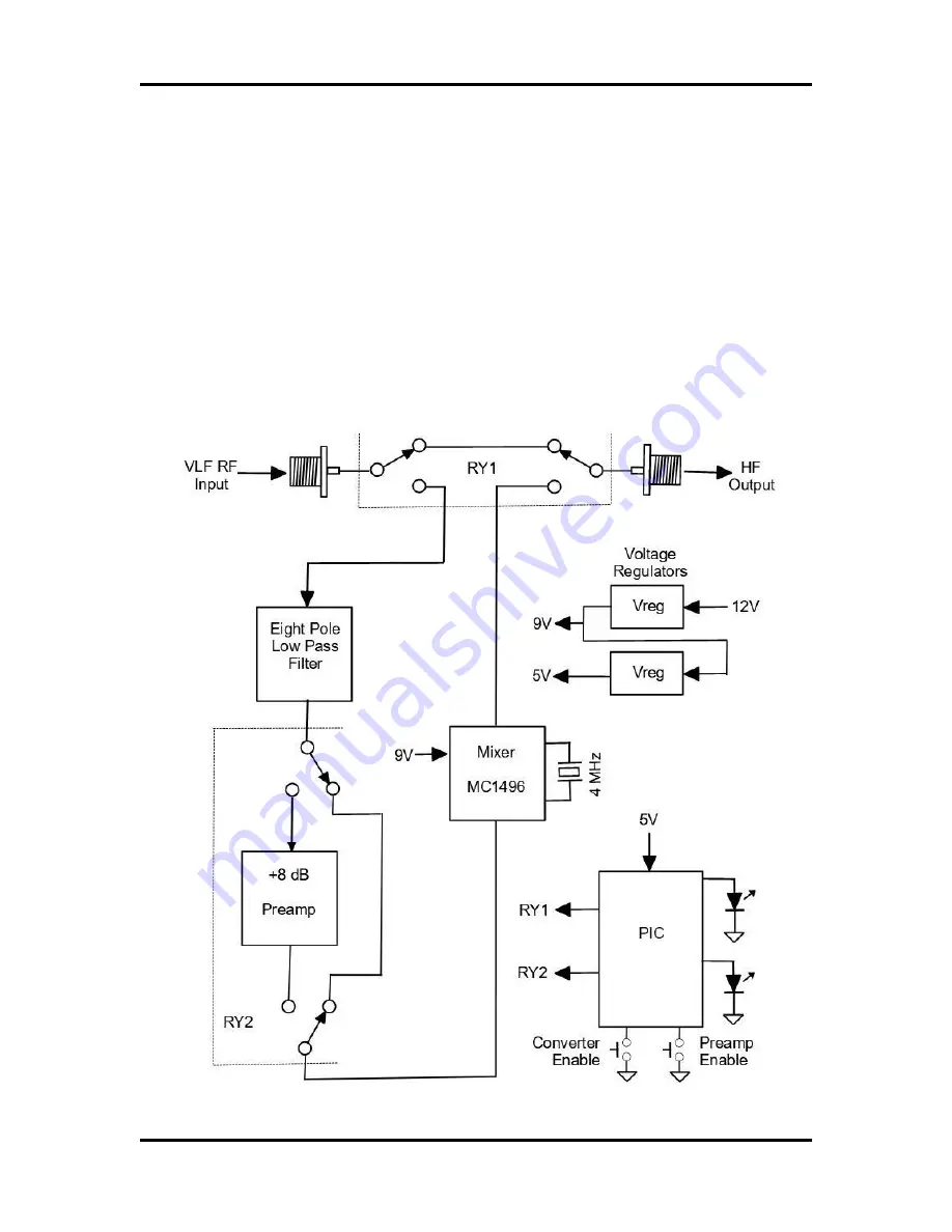
The internal components of the VLF-B are illustrated below. A radio antenna is connected to the
antenna input SO-239 connector. A bypass relay RY1 selects whether the signal passes directly
to the output SO-239 connector or into the converter circuitry. This allows the converter to remain
in line when not enabled. When enabled the signal first passes through a sharp cutoff 8 pole low
pass filter. The filter has a 3 dB corner frequency at approximately 450 KHz. After the LPF, the
signal is steered either through or around an 8 dB preamplifier by RY2. After that the signal
passes though the MC1496 converter mixer circuit where it is mixed with a 4 MHz BFO effectively
converting a VLF range of 10 KHz to 500 KHz to an HF range of 4.010 MHz to 4.5 MHz. From
there it passes through RY2 to the output SO239 connector. A Microchip PIC processor monitors
two front panel pushbuttons and converts button presses to relay selection for converter and
preamp enable. The current selection is shown via two front panel LEDs which are also controlled
by the PIC. The converter runs on a 12 volt DC supply; two on board regulators produce 9V and
5V to power the mixer and PIC processor.
VLF-B User Manual
11/30/2023 Rev 1.0
Page 3