Document K32903(12) | Date: March 25, 2020 | DRF: 5394
2797
User Manual
Models: InviCell Standard and InviCell Plus with SignipHy™pH Monitoring System
G210 InviCell
CO
2
/O
Incubator
Only
Page 1: ...Document K32903 12 Date March 25 2020 DRF 5394 2797 User Manual Models InviCell Standard and InviCell Plus with SignipHy pH Monitoring System G210 InviCell CO2 O2 Incubator Only ...
Page 2: ... Applicable Part Numbers 14 Significant Performance Characteristics 14 Operation Principle 14 User Profile 14 Dish Inserts 15 Chamber Heating 15 Chamber Lid 15 Preparation Chamber 15 Section 5 Product Overview 16 Main Components 16 Supplied Accessories for G210 InviCell Standard 17 Accessory Order Codes 18 Specification Table 19 Section 6 G210 InviCell Plus with SignipHy pH Monitoring System 20 Ex...
Page 3: ...nging the Temperature Setpoint 27 Changing the Gas Setpoint 27 Section 9 Settings 28 Changing the Date and Time 28 Ethernet Settings 29 Changing the Preparation Chamber Settings 29 Changing Language 29 Changing Basal Body Temperature 29 Security Settings 30 Access Levels 31 Edit User 32 Change Password 32 Create a New User 33 Delete User 33 Log Out 33 Lost Password 33 Alarm 34 External Alarm Conne...
Page 4: ... Regulator 41 O2 Gas Regulator 41 Gas Consumption 42 Touchscreen 42 Section 12 Maintenance 43 Preparation at the Point of Use 43 Periodic Cleaning 43 Disinfection 43 Drying 43 Sterilizing the Dish Inserts 44 Validation Check 44 Gas Sample Port 45 Chamber Lid Plug 46 Verification of Gas Concentration in Chambers 46 Temperature Calibration 47 Section 13 Service 48 Service plan 48 On screen Prompts 4...
Page 5: ...nmental Protection for Disposal of the Product 50 Recyclable Components 50 Section 15 Warranty Information and Limits on Liability 51 Section 16 Returning Product to CSI for Repair 52 Customer Service Contact Details 53 US Only Customers Contact Details 53 ...
Page 6: ...mission nor is liable for direct indirect incidental or consequential damages arising out of the use or inability to use this manual The information in this manual is current at the time of publication Our commitment to product improvement requires that we reserve the right to change equipment procedures and specifications at any time The latest version of the User Manual can be downloaded from or...
Page 7: ...nected DO NOT disassemble or modify any part of the G210 Invicell or substitute any component for any other Doing so may result in damage to samples This voids the warranty and or service contract WARNING To avoid the risk of electric shock this equipment must only be connected to a mains supply with protective earth WARNING Not to be used in a patient environment WARNING Use of accessories transd...
Page 8: ...of the failure has not been identified Protect the power cord from being damaged or being restricted in any way Unplug the power cord from the wall socket or at the rear of the instrument to disconnect the mains supply Make sure that CO2 and N2 gas supply pressures are maximum 1 0 bar and not below 0 5 bar Always keep the red cap on unused gas inlets at the back of the unit and the protection cap ...
Page 9: ...gnetic environment guidance Electrostatic discharge ESD IEC 61000 4 2 4 kV contact 2 4 8 kV air 2 4 kV contact 2 4 8 kV air Floors should be wood concrete or ceramic tile If floors are covered with synthetic material the relative humidity should be at least 30 Electrical fast transient burst IEC 61000 4 4 1 0kV Burst Potential Mains 0 5kV Burst Potential Signals Control 1 0kV Burst Potential Mains...
Page 10: ...res m Field strengths from fixed RF transmitters as determined by an electromagnetic site survey a should be less than the compliance level in each frequency range b Interference may occur in the vicinity of equipment marked with the following symbol NOTE 1 At 80 MHz and 800 MHz the higher frequency range applies NOTE 2 These guidelines may not apply in all situations Electromagnetic propagation i...
Page 11: ...rs within the European Union and associated states have taken the necessary steps to comply with the directive 2012 19 EU on waste electrical and electronic equipment WEEE The instrument when reaching its end of life must be collected and recycled separately from other waste according to national requirements Please contact a local CooperSurgical distributor for instructions Environmental implicat...
Page 12: ... the order of a licensed healthcare practitioner Warranty label Ethernet Sample Port Sample port GAS MAX 1 BAR Gas Inlets CO2 N2 Static sensitive ESD Fuse EC REP Authorized Representative in the European Community Humidity limitation for storage and use Non condensing Temperature limit for storage and use Max 1 week at 50 C 95 5 50 C 5 C ...
Page 13: ...acclimatize for two hours before installation To maintain a device setpoint between 35 40 C the preferred ambient temperature should be between 20 30 C DO NOT use the incubator at ambient temperatures exceeding 30 C as this may compromise the incubation process This unit is designed for use at altitudes under 2 000 meters HANDLE WITH CARE WARNING RED INDICATES ROUGH HANDLING IF RED NOTE ON THE BIL...
Page 14: ...50mm deep x 180mm high with a weight of 53kg maximum Indications for Use The G210 InviCell Plus with SignipHy pH Monitoring System is a bench top incubator that is intended to provide a controlled environment at or near body temperature and gas levels CO2 O2 and N2 for the development of gametes and or embryos during In Vitro Fertilization IVF Assisted Reproductive Technology ART treatments The G2...
Page 15: ...ch lid has a sensor that when opened will disconnect the gas flow to minimize ambient air entering the gas system The gas flow restarts immediately after closing the lid The silicone plugs 2 in the lid of each chamber are for the collection of gas samples These plugs should be replaced when penetrated a maximum of 5 times Preparation Chamber The Preparation Chamber 3 is intended to be used for the...
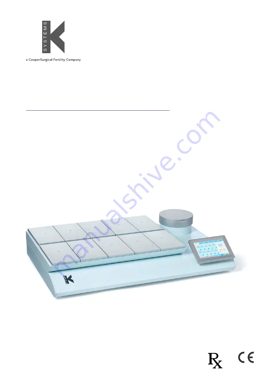
Page 16: ...uct Overview Main Components Components 1 Incubator Chambers 2 Touchscreen 3 Preparation Chamber 4 Origio Gas Line Filter 4 2 3 1 G210 InviCell Standard and Plus models front view G210 InviCell Standard and Plus models raised top section ...
Page 17: ...be Sealing Rings Silicone Tube 3m Gas sampling coupling 1 power cord 1 LAN cable 3m 1 packet of Chamber Lid plugs 10 pieces 1 USB drive containing K Link software Components 5 Product label 6 Mains connection with fuse 7 Ventilation holes 8 Gas inlet connectors 9 Alarm output 10 Ethernet connector External computing devices connected to the Ethernet on the unit must only be Limited Power Source an...
Page 18: ...r 59922 Lid Plugs bag of 10 59901 1 Lid Seal for culture chambers 59902 1 Lid Seal for Preparation Chamber 59688 Gas sampler coupling 11103 G100 Gas Analyzer 11006 Solid Temperature Sensor use with K Systems F100 Thermometer 59655 XLR6 Receptacle Connector 32903 G210 User Manual 60017 Connector for External CO2 sensor MTG Plus models only 60014 Connector for External CO2 sensor Vaisala Plus models...
Page 19: ...ange temperature and gas Filter HEPA VOC Origio Gas Line Filter IP class IP30 Overvoltage category Transient overvoltage II Pollution degree rating for electrical equipment 2 Power specifications 100 240 VAC Max consumption 270W Voltage L N PE AC 100 240VAC Class 1 type B Frequency 50 60 Hz Current 3A Mains supply voltage fluctuations Up to 10 of the nominal voltage Fuses 100 250V UL Listed Mains ...
Page 20: ...erSurgical or by persons authorized by CooperSurgical only Component 1 Connection for external CO2 sensor 2 Connection for external pH monitoring SignipHy 3 Data connection for external thermometer and power 4 Power connection for external thermometer and power External Sensors pH CO2 The following external sensors can be used with the G210 InviCell Plus External pH SignipHy TrakStation External C...
Page 21: ...unc pH Order code 23060 1 Dish Insert Falcon pH Order code 23061 1 Dish Insert Vitrolife pH Order code 23079 Dish Insert LifeGlobal Order code 23080 External Temperature Equipment needed 25 Pin D Sub male connector prepared for soldering 24VDC power supply Additionally Supplied Accessories for G210 InviCell Plus with SignipHy pH Monitoring System Connector for GMP251 Carbon Dioxide Probe from Vais...
Page 22: ...ure etc settings are as desired using the Settings Menu on the touchscreen After 30 minutes the unit will be at a constant working temperature and air flow see Changing the Temperature Setpoint on page 27 6 Set correct date and time before connecting to the network LAN WARNING Use only pure CO2 and pure N2 gas Use of other gases could result in serious injury Make sure that gas supply pressures ar...
Page 23: ...h Insert The use of Dish Inserts requires temperature calibration with the Dish Insert in place see Dish Inserts on page 15 1 Place the Dish Inserts in the chamber and close the lid 2 Wait 30 minutes for the Dish Inserts to heat up 3 Open the chamber lid 4 Place the culture dishes containing gametes or embryos on the Dish Inserts ensuring they are placed securely in the correct milled grooves 5 Cl...
Page 24: ...int Settings Log Menu Calibration Service Advanced View Alarm Date and Time Advanced Menu 1 Press Advanced 1 in the main menu Main Menu The main screen provides an overview of the temperature and gas concentrations inside the incubator 1 ...
Page 25: ...n about its status 2 The same information appears on the screen when a chamber lid is opened 3 Press Edit 1 to edit chamber information Edit Chamber Information 1 Press Occupied 1 and type in the text fields 3 When a text field is pressed a keyboard appears on the screen 2 All fields Patient ID Surname First name and Staff ID are limited to 10 characters 3 Press Free 2 to leave the chamber vacant ...
Page 26: ...re see below image over a three hour period 2 1 Setpoint 1 The Setpoint tab shows the setpoints for temperature and gas concentration Press the Edit button for Temperature 1 or for Gas 2 2 Only administrators and advanced users have access to change the setpoints Select a user and press OK 3 1 2 3 3 Press Level button 2 to return to temperature and gas concentration ...
Page 27: ...ature Setpoint Adjust the temperature setpoint by pressing the arrow buttons Press Save 1 Changing the Gas Setpoint 1 Adjust the gas setpoint by pressing the arrow buttons Press Save 1 4 1 1 2 It is recommended that gas concentrations are checked after changing the gas setpoint ...
Page 28: ...ettings 6 7 Language 7 8 Basal Body Temperature BBT settings 8 To change some of these settings requires a login see Security Settings on page 30 and Access Levels on page 31 Changing the Date and Time Select the date or time button 1 Adjust the time by pressing the or 2 Press OK 1 1 3 Select 12 or 24 hour time format 4 Press OK 1 1 5 Adjust the date by pressing the or 6 Press OK 1 1 ...
Page 29: ...4 Press Save 3 Changing the Preparation Chamber Settings Select the Systems button from the settings menu Changing CO2 regulator O2 regulator and gas supply to the Preparation Chamber on or off 1 2 3 Changing Language Select the Language button from the settings menu Choose the preferred language in the language menu Changing Basal Body Temperature Select the BBT button from the settings menu 1 Tu...
Page 30: ...tings In order to prevent unauthorized changes to setup parameters the unit uses different access levels In the security menu new users can be created and assigned access levels 1 Select the Admin user 1 and turn the security on 2 or off 3 2 The default password for admin is 1234 1 2 3 8 Adjust both the TMax and the TMin values by pressing the up and down arrows 7 9 Press Save 8 A short explanatio...
Page 31: ... password Calibration Create new users Edit users Delete users Reset filter counter When attempting to change a parameter that requires authorization the login window will pop up on the touchscreen Leaving a topic that requires a login will automatically log the user out 1 Select the access level for the user Advanced User or Administrator 1 2 Enter the user s data 2 There are 10 characters for Su...
Page 32: ...rd can be edited here Press Save 2 when done Change Password 1 Press Change password 1 to change the admin password 2 Enter the current password 2 Enter the new password twice 3 3 The password must be between 4 and 10 characters long 4 Press OK 4 1 2 3 4 5 If an incorrect password is entered twice these warnings appear ...
Page 33: ...firm OK to delete a user Log Out 1 In the Security window press Logout 1 2 Administrators or Advanced Users will be automatically logged out after 5 minutes of inactivity 1 Lost Password If all Administrator passwords are lost please contact a sales representative or local distributor to acquire a special login Please have the unit s serial number at hand as the special login is unit specific ...
Page 34: ...external alarm connector which can be connected to a monitoring device The connector can be connected to either a voltage source or a current source 1 External Alarm Connector This section for installers of third party monitoring systems XLR6 Receptacle Connector Alarm 1 Position 1 2 responds to Gas alarm Alarm 2 Position 3 4 responds to Pressure alarm Alarm 3 Position 5 6 responds to Temperature ...
Page 35: ...ettings K Link must be launched with elevated administrative privileges To launch K Link with elevated administrative privileges right click on the K Link icon then click Run as administrator There may be a prompt to enter alternative credentials Consult the IT Department for further details The K Link loading screen is displayed for a few seconds while the software loads Device Connection The dev...
Page 36: ...ever it can take up to 1 minute before any graph can be seen Measurement Section The measurement section displays the measurements retrieved from the device every 30 seconds the connection status of the device a setting to enable or disable email notifications if an alarm is triggered and an Open Log button to explore the folder containing the file where the logs are being saved Alarm Display Sect...
Page 37: ...wever the Y Axis can be adjusted by holding down the left mouse button and dragging a box around an area of interest then releasing the button A single left click anywhere on the graph will reset to the original scale Level Tab The Level tab displays a graph of the gas concentration levels over time ...
Page 38: ...ssure Tab The Pressure tab displays a graph of the device measurements over time Daily Average Tab The Daily Average tab displays daily averages for the individual measurements collected from the device every 24 hours ...
Page 39: ...e last 50 individual alarms Mail Tab The Mail tab allows users to configure K Link to email notifications about alarms and service information NOTE It is recommended to configure K Link to use the specified mail server Consult the IT Department for mail server information ...
Page 40: ...al number information It also shows counters to indicate when a general service check a filter change should be conducted When the counters time out the service alarm light is triggered and will remain active until all counters are reset K Link refreshes information displayed in the service tab every 10 minutes ...
Page 41: ...al gas concentration is higher or lower than setpoint Check CO2 setpoint Actual gas concentration is higher or lower than setpoint Calibration of the gas concentration is needed Poor CO2 gas regulation Lid s are left open Close lid s Seals are damaged or missing on lid s Check the seals are intact CO2 concentration alarm CO2 gas concentration more than 1 from setpoint Allow system to stabilize by ...
Page 42: ...sample port Remove the coupling and replace the protection cap see page page 45 The sample connector has not been fully released Press down the ejector ring on the connector to close the sample port CO2 is decreasing and O2 is increasing during gas sampling G210 is emptied of gas Turn off G210 Restart the G210 Let gasses stabilize Wrong gas concentration in one chamber Lid plug has been penetrated...
Page 43: ...inting cloth with purified or sterile water and wipe all surfaces for a minimum of one 1 minute per chamber If needed use additional cloths if cloths become visibly soiled 3 Allow chamber to air dry 4 Visually inspect each chamber for the absence or presence of remaining soil While inspecting give particular attention to verifying soil has been removed from the hard to clean areas If soil is prese...
Page 44: ...ating correctly Gas Calibration It is very important the the G210 is not emptied of gas during the gas calibration procedure To do so will cause unstable gas levels and gas flow and will result in a considerable time before the gas concentration is recovered and becomes reliable and stable again To ensure the G210 is not emptied of gas during the gas sampling please follow the below instructions T...
Page 45: ...the tubing 3 Remove the protection cap from the sample port 4 Connect the coupling to the sample port 5 Collect the gas sample using the gas analyser 6 Stop the gas analyser pump 7 Record the gas concentration reading 8 Disconnect the coupling from the sample port 9 Replace the protection cap If calibration is needed adjust the value on the calibration wait for the gas to stabilise and re test Aft...
Page 46: ...10th Chamber 5 1 Connect a short length of tubing to the gas analyser input 2 Connect a 25 gauge needle to the tubing 3 Penetrate the required chamber through the silicone plug 4 Collect the gas sample using the gas analyser 5 Stop the gas analyser pump 6 Remove the needle from the silicone plug 7 Record the gas concentration reading 8 Wait 2 minutes between chamber sampling 9 Repeat for the remai...
Page 47: ...ure Calibration Procedure 1 Open the lid and place the calibrated temperature sensor at the bottom of the chamber 2 If the chamber is used with a dish insert place the sensor on the dish insert 3 Close the lid 4 Read the temperature when the temperature reading on the external thermometer is stable to the second decimal 5 Adjust the calibration setpoint by pressing the icon representing the reques...
Page 48: ...years Replace Origio Gas Line Filter X Replace HEPA Inline Filter for CO2 gas X Replace HEPA Inline Filter for N2 gas X Replace O2 sensor X Temperature and gas calibration X Replace Pump X Replace CO2 sensor X Gas calibration should be performed after replacing O2 and CO2 sensors On screen Prompts 3 2 1 WARNING DO NOT disassemble or modify any part of the G210 InviCell Section 13 Service The servi...
Page 49: ...essing and treating infectious substances it might be contaminated The used Gas Line Filter should be placed in a sealed plastic bag and labeled as biohazard material then disposed of according to local requirements 2 3 Ensure the direction of flow shown on the Origio Gas Line Filter label 3 is consistent with the flow direction 4 shown inside the filter compartment 4 Place the Origio Gas Line Fil...
Page 50: ...o Gas Line Filter can be discarded as electrical waste after cleaning and disinfection Please note that Origio Gas Line Filters must be discarded in accordance with the applicable national regulations for special solid waste If any electronic component is no longer serviceable it must be sent back to CooperSurgical to be destroyed in an environmentally safe way Do not dispose of with normal waste ...
Page 51: ...changes to a product will void that product s warranty CSI s warranties do not apply to any single or limited use disposable or consumable components or items CSI is not responsible for and the owner and operator of the product shall defend indemnify and hold harmless CSI from and against all claims damages and other losses resulting from the improper servicing maintenance repair use or operation ...
Page 52: ... All used products must be cleaned and sterilized prior to shipment A signed decontamination declaration may be required All products should be carefully and adequately packed preferably in original packaging Replacement items or additional repairs will be invoiced All packaging should be clearly labeled with the RMA number and statement Urgent Returned Items for Repair Return Address Research Ins...
Page 53: ...o CSI for Repair Customer Service Contact Details Tel 45 46 79 02 02 Fax 45 46 79 03 02 E mail customerservice origio com coopersurgical com US Only Customers Contact Details Tel 800 243 2974 Fax 800 262 0105 coopersurgical com ...
Page 54: ......
Page 55: ......
Page 56: ......