background image


51

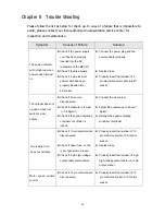
Overload lamp light 
on 

z


Check if the tooling horn 
cracked 

z


Check if AC cooling fans 
does not work cause of the 
tooling horn temperature too 
high   

z


Replace the tooling horn 


z


Replace the cooling fan 

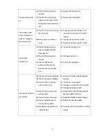
The working roller 
and/or tooling horn 
does not rotated or 
smoothly turning 

z


Check if 10 pin control cable 
disconnected 


z


Belt or chain is broken or 
loose 

z


Properly insert the terminal of 10   

pin control cable into 10P control 
socket 

z


Change the new belt or chain. 

z


Adjust the tension of belt or chain 

Noise when 
ultrasonic on 

z


Check if the tooling horn 
does not tighten with the 
transducer kit 

z


Check if the tooling horn 
cracked 

z


Check if without any 
workpiece between the 
working roller and tooling 
horn 

z


Tighten the tooling horn 


z


Change a new horn 


z


Put into the workpiece 

The result of welding 
are instable 

z


Check if line source instable 

z


Check if air source instable 

z


Check if horn or working 
roller is worn down 


z


Check if horn uneven with 
working table 

z


Check if roller is bad level 

z


Check if working roller or 
horn turned too faster 

z


Unsuitable roller pattern of 
cutting design 

z


Install a constant voltage regulator 
as need 

z


Let the air source stable 

z


Change or re-grind the horn surface 

z


Change the working roller 

z


Adjust and control the accuracy of 

the level within 0.02 mm.


z


Adjust the height of outer bracket


z


Reduce the working speed


z


Re-design the roller pattern or cutting 
design 

Summary of Contents for KS-2010

Page 1: ...ING MACHINE KS SERIES Operation Manual Please read this manual carefully before use for an appropriate way of using this product After reading please keep this manual properly MODEL KS 72 KS 85 MODEL KS 2010 KS 3010 ...

Page 2: ...Diagram and Description of Each Part 10 6 3 Pneumatic Circuit Diagram 29 6 4 Wiring Diagram 30 6 5 Circuit Diagram 34 Chapter 7 Description of Operation 7 1 Block Diagram of Machine System 38 7 2 Notices of Operation 39 7 3 Installation and Working Preparation 41 7 4 Installation and Replace the Tape Strip Holder 42 7 5 Installation and Replace the Working Roller 44 7 6 Replacement of the Tooling ...

Page 3: ...ultaneously fibers mixed woven or non woven cloth simultaneously or separately There are more than 1000 kinds of patterns to choose from Special patterns designed by customers are also possible 1 2 Mechanism Principle The ultrasonic mechanical vibration is amplified and transmitted to the horn surface through a booster and then on to the horn At the point which the pattern roller and the horn meet...

Page 4: ... EC amend by 2006 42 EC Low Voltage Directive 73 23 EEC amend by 2006 95 EC and Electromagnetic Compatibility Directive 89 336 EEC amend by 2004 108 EC and is also meet the following standards EN ISO 12100 1 EN ISO 12100 2 EN 60204 1 ISO 14121 1 ISO 14121 2 1 5 Please read this Operation Manual carefully before use ...

Page 5: ...g Lamp On Ultrasonic Stop Working Speed 0 18 M min Welding Width 1 0 70 mm 1 0 48 mm 1 0 10 mm Welding Thickness of Material 0 03 1 5 mm 0 03 1 5 mm 0 03 1 5 mm Alternative Roller Φ 51 mm x 2 Φ 51 mm x 3 Φ 51 mm x 1 Φ 51 mm x 2 Φ 60 3x10 mm Horn Size ψ79 mm ψ54 mm ψ24 mm ψ28 mm Machine Dimension W 1200 L 540 H 1160 mm W 1200 L 540 H 1060 mm W 1200 L 540 H 1280 mm Machine Weight 150Kg 130Kg 120Kg N...

Page 6: ...f horn during operation Warning High Voltage The capacitors in the electrical control unit or the generator are electrically charged if the machine shuts down seek professional maintenance Warning Rolling Keep hands away During operation do not place your hand inside the area where the ultrasonic horn is rolling to avoid being injured or burned 1 Do not put finger between working roller roller bra...

Page 7: ... please do not place the hand or any part of the body near the moving parts to avoid collisions injuries or being rolled into the machine 4 7 Unauthorized personnel are not allowed to replace moving parts or other components Component replacement should be performed by professional personnel 4 8 Install the machine on a flat and rigid surface 4 9 The machine should be properly grounded 4 10 Please...

Page 8: ... the machine on a pallet before being transported by the forklift z If the machine is moved by persons please pay attention to the mass center of the machine to avoid toppling and injury While placing the machine on the surface or working platform please pay attention to your hands 5 3 Installation z Before installation if there is any obvious exterior damage to the machine please contact the comp...

Page 9: ...I O KING ULTRASONIC CO LTD ULTRASONIC LACE SEWING MACHINE A AMPLITUDE I O KING ULTRASONIC CO LTD ULTRASONIC LACE SEWING MACHINE A Chapter 6 System Function and Specification 6 1 Out look Dimensions A KS 72 B KS 85 ...

Page 10: ...9 KING ULTRASONIC CO LTD ULTRASONIC LACE SEWING MACHINE I O 焊頭轉速調整 連續 腳踏開關 5 6 4 2 3 1 0 5 7 7 電源指示燈 6 過載指示燈 功率調整 4 2 3 1 0 8 10 9 花輪轉速調整 振幅表 8 10 9 A 8 4 6 5 7 2 3 1 10 9 0 C KS 2010 KS 3010 ...

Page 11: ...10 AMPLITUDE I O KING ULTRASONIC CO LTD ULTRASONIC LACE SEWING MACHINE A 6 2 Structural Diagram and Description of Each Part A KS 72 KS 85 Main M C ...

Page 12: ...11 ...

Page 13: ...12 ...

Page 14: ...sms which conveys the upper motor s power to working roller 9 Upper Transmit Shaft Link timing pulley and gear and convey the upper motor s power to working roller 10 Chain A component of transmission mechanisms which conveys the upper motor s power to working roller 11 Gear A component of transmission mechanisms which conveys the upper motor s power to working roller 12 Cylinder Lowers down or li...

Page 15: ... as possible the water must be drained everyday by pressing the push button up 21 Foot Switch Controls roller cylinder up down activities 22 Treadle Switch Switches on the operation of motor and ultrasonic 23 Safety Cover R Cover the motor transmission mechanism and electrical parts for safety concern 24 Foot Switch Switches on the operation of ultrasonic only 25 Transformer Unit Cover To support ...

Page 16: ...e melting materials from sticking on the horn surface And most importantly when cutting cloth it acts as a cushion to the horn surface and makes cutting cloth easier 38 Paper Tension Bar This is the mechanism which applies tension to the paper strip and keeps it straight while paper tape is passing through the working roller then to the puller roller 39 Paper Strip Guide Guides the paper strip tha...

Page 17: ...r horn to upper working surface 50 Booster Outer Bracket To support and fix the transducer kit 51 Booster Inner Bracket To support and fix the transducer kit 52 Plastic Washer To restrain the noise of resonance from the vibration 53 Transducer Kit Including the transducer and booster Transforms the electrical oscillation energy to mechanical vibration energy Caution There are 2 cooling fans beside...

Page 18: ...ng sockets for safety 60 Cable with 4P Connector Transmission of electrical power from the transformer unit to the generator 61 Cover To support and fix the generator with the working table 62 4P Socket Transmission of electrical power via cable connection 63 Frame To support and fix the mechanism and electrical parts 64 Adjustable Stand To fix the machine and adjust the level of machine 65 Soleno...

Page 19: ...defect please stop working and check 2 Overload Indicator If overload LED brightens the ultrasonic system must has some defect please stop working and check 3 Output Adjusting Knob The knob for adjusting ultrasonic vibration amplitude The higher the setting the easier the working is Usually it is set at scale 8 When turning the knob clockwise the amplitude will increase and the needle in the amper...

Page 20: ...tern of roller pressure of roller and the power setting of horn vibration It should be adjusted to match the feeding speed of roller if possible Otherwise the tool horn surface will be easily scratched by the roller 9 Fuse 10A 250V φ6 3 32 mm fuse inside the fuse holder each 10 Fan Guard To prevent the human body touching the AC fan 11 Enclosure To support and fix the electrical parts of the gener...

Page 21: ...20 焊頭轉速調整 8 4 6 5 7 2 3 10 9 連續 腳踏開關 1 0 功率調整 振幅表 花輪轉速調整 8 4 6 5 7 2 3 10 9 電源指示燈 1 0 8 4 6 5 7 2 3 1 10 9 0 過載指示燈 KING ULTRASONIC CO LTD ULTRASONIC LACE SEWING MACHINE I O A C KS 2010 KS 3010 Main M C ...

Page 22: ...21 ...

Page 23: ...22 ...

Page 24: ...echanisms which conveys the upper motor s power to working roller 9 Timing Gear A component of transmission mechanisms which conveys the upper motor s power to working roller 10 Control Unit Please refer to P 27 Item D 11 Upper Transmit Shaft Link timing pulley and gear and convey the upper motor s power to working roller 12 Chain A component of transmission mechanisms which conveys the upper moto...

Page 25: ...Filter Connect it to an air source with an I D 5 16 8 mm hose then it will filter the air and supply clean dry air into the system Caution The filter may accumulate water in the cup As much as possible the water must be drained everyday by pressing the push button up 23 Foot Switch Controls roller cylinder up down activities 24 Solenoid Valve Receive instruction from Item 23 foot switch to drive r...

Page 26: ...ler and should only be performed by a trained technician or engineer 38 Paper Strip Guide Guides the paper strip that is below the workpiece used especially in cutting cloth and in transporting material to the puller roller 39 Horn Transmits and amplifies the ultrasonic vibration energy from the booster horn to upper working surface 40 Booster Outer Bracket To support and fix the transducer kit 41...

Page 27: ... Transmission of high voltage ultrasonic energy to the oscillator unit 49 Safety Cover Back Cover the generator including sockets for safety 50 Cable with 4P Connector Transmission of electrical power from the transformer unit to the generator 51 Cover To support and fix the generator with the working table 52 4P Socket Transmission of electrical power via cable connection 53 Frame To support and ...

Page 28: ...g of horn vibration It should be adjusted to match the feeding speed of roller if possible Otherwise the tool horn surface will be easily scratched by the roller 2 Roller Speed Adjusting Knob The knob for adjusting the feeding speed of sealing roller and puller roller It should be adjusted to match the feeding speed of tool horn The feeding speed will be increased as the knob is rotated clockwise ...

Page 29: ...over Cover the electrical parts of control unit for safety 10 Control Unit Stand To support and fix the control unit 11 Power Switch It s a power source switch Push the power on and the lamp inside will be illuminated 12 Control Panel To fix the power switch 13 Fuse 10A 250V φ6 3 32 mm fuse inside the fuse holder each 14 Fan Guard To prevent the human body touching the AC fan 15 Enclosure To suppo...

Page 30: ...ng Controller Speed Adjusting Controller Air Filter Pressure Regulator Muffler Muffler Solenoid Valve Air Source Pressure Gauge Air Filter Pressure Regulator Muffler Muffler Solenoid Valve Foot Switch Air Source Cylinder Speed Adjusting Controller Speed Adjusting Controller Pressure Gauge ...

Page 31: ...30 6 4 Wiring Diagram A MAIN WIRING DIAGRAM A 1 KS 72 ...

Page 32: ...31 A 2 KS 85 ...

Page 33: ...OVERLOAD LAMP OR RD BK 10P 5 5 8 UB 00004 CONTROL UNIT 7 6 MOTOR 1 B 1 6 FOOT SWITCH 2 4 3 1 TREADLE SWITCH 2 WH BK GL FAN2 1 3 GN ROLLER SPEED VR1 0 5mm 2C L 1 8M 0 5mm 10C L 1 8M OSC 220 110 0 M1 M1 M1 M1 M1 0 110 240 230 220 OVERLOAD LED YL PU BL AC110V GN VR1 ROLLER SPEED HORN SPEED VR2 FUNCTION SW POWER LAMP WH BK 2 OUTPUT VR 1 RD GR WH OR BK BR YL SOLENOID VALVE AC110V FUSE CYLINDER FOOT SW ...

Page 34: ...RAIC DICA R34 R36 R35 R38 R33 R31 R32 R37 C19 C18 C17 R102 F101 L2 UB 90007 A C1 C17 F L1 BD1 TNR MC1 SW1 FUSE2 FUSE1 UB 20001 POWER TRANSISTOR ASSEMBLY SW3 T4 MDC C13 VL1 TR2 TR3 R24 R25 SOC 8 SOC1 7 4 3 1 2 6 5 4 3 2 1 SOC3 T1 VR2 GLUE VR1 RED SOC4 K1 SOC5 D13 D12 T3 T2 UB 10020 B GENERATOR WIRING DIAGRAM KS 72 KS 85 KS 2010 KS 3010 ...

Page 35: ...34 Ω 1 2W Ω 10W Ω 1 2W 6 5 Circuit Diagram A MOTOR SPEED CONTROL CIRCUIT DIAGRAM A 1 KS 72 UPPER MOTOR WORKING ROLLER ...

Page 36: ... MY2 TREADLE SW T2 A2 D1 D7 D2 D8 UB 00004 MY4 MOTRO 2 C3 C1 C2 R4 MY4 4 R5 C5 1 8 C4 C5 C4 R6 5 4 2 3 A6 C6 VR2 C8 MY2 1 FUSEI 0 5A D6 A10 R8 T1 R7 D1 R9 D2 A9 D5 D4 D3 IC 1 FOOT SW FAN AC 110V F F 7 MY4 3 A5 A 2 KS 72 LOWER MOTOR TOOLING HORN ...

Page 37: ...USEI 0 5A R7 T1 CONTROLL PACK 2 8 7 6 5 4 3 2 1 MY4 3 R6 C6 A5 A6 VR2 MY4 4 R5 C5 R4 C4 C1 C3 C2 C5 C4 MOTRO 2 C0NTROLL PACK 1 8 7 6 5 4 3 2 1 MY4 2 C1 R1 C2 R2 MY2 2 MY4 MY2 T3 T2 C7 AC 110V TREADLE SW A1 A2 D1 D2 D7 D8 B2 B1 B3 B5 B4 MY4 1 R3 C3 A3 A4 VR1 MOTOR 1 A 3 KS 85 KS 2010 KS 3010 ...

Page 38: ...37 FUSE FUSE B GENERATOR CIRCUIT DIAGRAM KS 72 KS 85 KS 2010 KS 3010 ...

Page 39: ...38 PAPERS FEDING SYSTEM ULTRASONIC GENARATION SYSTEM CONTROL SYSTEM DYNAMIC DRIVING SYSTEM POWER SOURCE SUPPORTER MECHANISM Chapter 7 Description of Operation 7 1 Block Diagram of Machine System ...

Page 40: ...tem can be damaged B Inspection on ROLLER 1 The blade pattern on the ROLLER should be kept sharp and in good condition Poor quality worn or rusty rollers should not be used to avoid bad processing and may also decrease the life of HORN with improper applying pressure 2 Please purchase the rollers made by our company to increase the machines performance If rollers of other companies are used please...

Page 41: ...atterns on the roller thus reduce the machines life As long as the processing quality of the working material is good adjust the pressure to be as low as possible to increase the lifespan of the HORN and the ROLLER D If the pointer in the ampere meter on the generator exceeds 1 5A it indicates that the ultrasonic oscillator system is abnormal Please stop the machine and restart after examination O...

Page 42: ... tightly fasten D Plug the 10P control cable of the machine into the 10P control socket of the generator and tightly fasten E Plug the 2P output power cable of the machine into the 2P output socket of the generator and tightly fasten F Plug another 2P cable of the machine into the 2P socket of the generator and tightly fasten for KS 2010 and KS 3010 only G Use copper wires to connect the ground of...

Page 43: ...on and Replace the Tape Strip Holder A Lift up the puller roller and working roller B Follow the Illustration to assembly or disassembly the different width tape strip holder guider and tapes STEP 1 STEP 2 STEP 3 STEP 4 ...

Page 44: ...t this time the working roller and horn are separated and the upper and lower puller roller are separated too D When the working roller is set well please individually put down the puller roller and the working roller E Let workpiece nylon or T C T R FABRIC put between paper and O P P tape and tread down the treadle switch the machine can be started to work ...

Page 45: ... long shaft innermost towards the inner side C Using 2 screws install the outer working roller bracket then tread down the left side foot switch again to lower down the roller bracket D Feed the workpiece in between O P P strip and paper strip and run the machine E Adjustment If the workpiece is not uniform across the width i e more pressure is applied one side than the other then adjust the heigh...

Page 46: ...changed using the following procedures and drawings A Switch off power supply B Raise up the roller bracket then remove the roller C Remove the protecting cover from the tooling horn D Hold the booster horn with an adjustable wrench and use a barb wrench hook in an counterclockwise direction Then release and remove the tooling horn Caution 1 Work at the rear side of the machine 2 Fan should be rem...

Page 47: ...er it is paralleled to the table surface or not If it is not then adjust the six screws in the horn holder to the correct position Notes the level of the HORN has been adjusted properly before it leaves the factory Adjust it with care until an inclined level is found by measurement If the level of the HORN must be adjusted please use the Dial indicator at least 0 01mm resolution for adjustment and...

Page 48: ...the workpiece and lower puller roller for running 3 Tread down the foot switch and check whether the ultrasonic vibrate or not There will be a sharp HISSING sound and the loading meter will indicate below 1 5A when the output knob is set to scale 10 When touching by hand slight heat and tingling will be felt on the horn surface the more pressure used the stronger feeling will be 4 Tread down the t...

Page 49: ...the foot switch which is located on the right side of the treadle At this stage only ultrasonic vibrate without the roller turning and only the position which is directly underneath will be sealed and the workpiece will not run C Methods of Adjustment In general there are many factors affecting the working results that depends on what functions we choose For example when we work continuous cutting...

Page 50: ...cordingly 3 Pressure Adjustment Pressure is very important when used in sealing and stamping It should match working speed and amplitude of horn Also the pressure of puller roller should be suitably adjusted or puckering will occur 4 Some Supplementary Methods in Sealing In sealing operations there may be some material that punks and twists In this case it will be helpful to change the paper tape ...

Page 51: ...into 4P socket The cylinder does not up down when foot switch L side actives z Check if Air source disconnected z Check if pressure is too low 0 5 Kg cm z Check if the speed adjusting controller of cylinder is locked z Connect the air source z Adjust the pressure up to above 1 Kg cm z Release the speed adjusting controller of cylinder The tooling horn does not oscillate z Check if 10 pin control c...

Page 52: ... if the tooling horn cracked z Check if without any workpiece between the working roller and tooling horn z Tighten the tooling horn z Change a new horn z Put into the workpiece The result of welding are instable z Check if line source instable z Check if air source instable z Check if horn or working roller is worn down z Check if horn uneven with working table z Check if roller is bad level z Ch...

Page 53: ...Check the whether there is leakage in the pneumatic circuit 5 Inspect whether the screws on each part are loose or not if so fasten them 6 Check whether the tooling horn is worn out 7 Check whether the working roller is worn out 8 Check whether the connector is loose Caution Because there are high voltage in both generator and Horn Transducer mechanism It is absolutely necessary to switch off the ...

Page 54: ...Manufacturer King Ultrasonic Co Ltd No 8 Wugong 5th Rd Xinzhuang Dist New Taipei City 24890 Taiwan R O C Tel 886 2 22980299 Fax 886 2 22980399 2011 02 Rev A1 ...

Reviews: