


REV. A
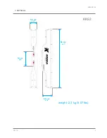
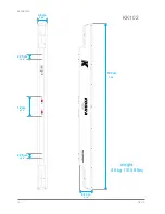
KK52/KK102
11
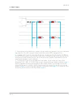
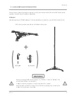
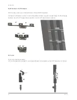
8. REAR PANEL
1
1
2
3
1)
Mounting screw holes. Most K-array mounting or flying accessories are designed to screw into the speakers
using these holes. The KK52 is equipped with two screw holes, while the KK102 is equipped with four.
2)
Impedance switch. Selects the impedance of the speaker. Impedance must be set to high (64 Ω for KK52 and
32 Ω for KK102) when speakers are driven by KMT active modules. Low impedance may be used when speakers are
driven by most KA series amplifiers (KA3, KA7, KA10). Please refer to your amplifier’s specifications to select the
correct speaker impedance for your configuration.
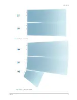
3)
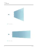
Coverage switch. Selects the vertical dispersion of the speaker. Flood coverage sets a wide vertical
diffusion angle of 60° (KK52) / 35° (KK102). Flood coverage is suggested for single speakers in diffused
(image 1)
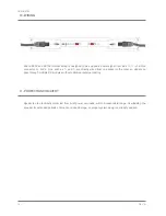
short throw applications, to obtain maximum diffusion with a minimum footprint. Spot coverage sets a narrower
vertical diffusion angle of 10° (KK52) / 7° (KK102). Spot coverage is recommended for long throw or monitoring
applications
(image 2)
. In most multi-speaker applications, set coverage to Spot
(image 3)
. A combination of Flood
and Spot may also be effective for downfill applications
(image 4)
.
Summary of Contents for Kobra KK52
Page 1: ...KK52 KK102 USER S MANUAL English Kobra ...
Page 2: ......
Page 4: ...KK52 KK102 REV A 4 ...
Page 6: ...KK52 KK102 REV A 6 ...
Page 12: ...KK52 KK102 REV A 12 9 COVERAGE Img1 Flood coverage Img2 Spot coverage ...
Page 13: ...REV A KK52 KK102 13 Img3 Array spot coverage Img4 Array Downfill application ...
Page 22: ...KK52 KK102 REV A 22 ...
Page 25: ...KMT12 KMT18 USER S MANUAL English ...
Page 26: ...KMT12 KMT18 REV A 2 ...
Page 28: ...KMT12 KMT18 REV A 4 ...
Page 30: ...KMT12 KMT18 REV A 6 ...
Page 34: ...KMT12 KMT18 REV A 10 61 cm 46 5 cm 47 5 cm 24 02 18 31 18 70 weight 27 6 kg 60 85 lbs KMT18 ...


