


3-4
NOTE:
To prevent the tape from damage, turn the guide rollers
slowly.
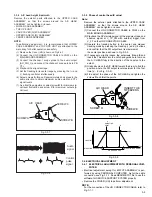
(7) By operating the tracking button (both in + and - directions)
in the manual tracking mode, vary the output level of the
FM waveform from maximum to minimum and vice versa to
confirm that the waveform varies nearly in a flat shape.
(8) When the FM waveform breaks in the level varying process,
subtly adjust the height of guide rollers at every breaking
point so that the waveform varies as flat as possible.
Repeat the above steps 6. and 7. several times to confirm
that the waveform is flat as a whole.
(9) Playback the SP stairstep signal of alighment tape and ad-
just the tracking control to maximize the FM waveform,
confirm that FM waveform variation is always flat.
(10) Record the signal and play it back in both of the SP and EP
modes, and confirm that the FM waveform is flat in both
modes.
NOTE:
Among the above-mentioned adjustment steps, the
items of No.9 and No.10 are needed for the EP model
only.
Fig.3-3-5
Fig.3-3-6
(11) Through the above steps, confirm that there occur no wrin-
kling and damage in the tape around the PINCH ROLLER
and TU GUIDE POLE whenever the deck is in operation of
Loading/Unloading, Search Rewind and at mode change
from Search Rewind to play mode. If wrinkling or damage
in the tape occurs around the TU GUIDE POLE, adjust the
angle (slant) of the A/C HEAD to the tape. So that the tape
normally runs along the lower flange of the GUIDE POLE.
CH-2
CAUSER BY WRONG HEIGHT
OF SUPPLY GUIDE ROLLER
CAUSED BY WRONG HEIGHT
OF TAKE-UP GUIDE ROLLER
FLATTEN WAVEFORM.
1 field
CORRECT VARIATION OF WAVEFORM
BAD VARIATION OF WAVEFORM
Fig.3-3-3
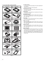
3.3.3 Tape pattern
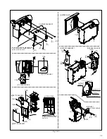
Remove the exterior parts attached to the UPPER CASE
ASSEMBLY so that the guide roller beside the DRUM ASSEMBLY
can be rotated.
• LOWER CASE ASSEMBLY
• TOP OPE UNIT
• CASE COVER(S),(M) ASSEMBLY
• UPPER CASE (S),(M) ASSEMBLY
NOTE:
In performing adjustment, it is recommended that LOWER
CASE ASSEMBLY and TOP OPE UNIT are attached to the
main body for better operation and safety.
Fig.3-3-4
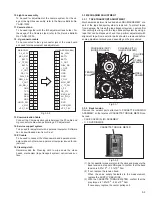
(1) Remove the Cover (JIG) shown on Fig.3-4-1.
(2) Connect the JIG CONNECTOR CABLE to CN25 on the
MAIN BOARD ASSEMBLY as shown on Fig. 3-2-2.
(3) Observe signal at V_TP_FM with external trigger from
V_FF on the JIG CONNECTOR CABLE.
(4) Playback the SP stairstep signal of the alignment tape and
maximize the FM waveform by the tracking button.
(5) Set the tracking control to the center position by simulta-
neously pressing the tracking (-) and (+) buttons and max-
imize the FM waveform by the tracking button.
(6) If the observed FM waveform is not flat, adjust the height of
the SUPPLY of TAKE-UP GUIDE ROLLER with the roller
driver.
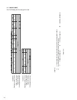
BACK TENSION
0.97x10
-3
- 1.71x10
-3
N
•
m
(10-17gf·cm)
PLAY TORQUE
1.47x10
-3
- 2.45x10
-3
N·m
(15-25gf·cm)
POLE BASE (TU)
(GUIDE ROLLER)
POLE BASE (SUP)
(GUIDE ROLLER)
JIG CONNECTOR CABLE
MAIN CN25 - JIG BOARD
12PIN(V_TP_FM)
13PIN(V_FF)
ALIGNMENT TAPE